
A prototype powers up cleanly on the bench, the microcontroller runs, and the voltage rail reads exactly 3.3 V. Then the enclosure is closed, the input adapter rises to its maximum voltage, and the regulator becomes too hot to touch.
In another design, a switch-mode converter solves the heat problem but introduces ripple that appears as noise in an analog measurement. A low-noise LDO added afterward improves the signal, yet battery life is shorter than expected.
These are not unusual mistakes. Selecting a regulator is not simply a matter of matching an output voltage. The right choice depends on voltage difference, current, heat, noise, battery conditions, transient behavior, board area, and even the layout skills available to the designer.
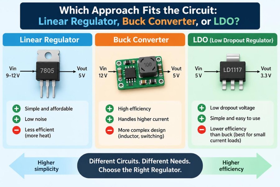
Linear regulators, low-dropout regulators, and buck converters can all produce a stable lower DC voltage. They do it in fundamentally different ways, which means each one fits some circuits far better than others.
⚡ Start with the job a regulator must do
A voltage regulator accepts an input supply that may vary and delivers an output rail held near a target voltage. It must do this while the load current changes, the input changes, and the surrounding temperature changes.
For example, a 3.3 V sensor and microcontroller rail may be fed from a 5 V USB source, a 12 V adapter, or a Li-ion battery. Those sources have different voltage ranges and different consequences for regulation.
The first design question is therefore not “Which regulator is best?” It is “What conditions must this rail survive and meet?”
📦 The three approaches at a glance
| Approach | Basic method | Typical strength | Main trade-off |
|---|---|---|---|
| Linear regulator | Dissipates excess voltage as heat | Simple, low-noise rail | Efficiency falls with large voltage drops |
| LDO | A linear regulator that works with low input-output headroom | Useful when input is close to output | Still loses power as heat |
| Buck converter | Switches energy through an inductor | High efficiency at substantial step-down ratios | More ripple, parts, and layout sensitivity |
An LDO is not the opposite of a linear regulator. It is a specific kind of linear regulator. Many comparisons say “linear regulator versus LDO,” but the useful distinction is usually a conventional linear regulator versus a low-dropout one.
🔥 Understand where lost power goes
For a linear regulator, the approximate power dissipated inside the device is:
P_loss = (V_in − V_out) × I_outIf a circuit draws 300 mA at 3.3 V from a 12 V source, the regulator drops 8.7 V. It dissipates about 2.61 W, which is far beyond what many small packages can safely handle without substantial thermal design.
That energy does not disappear. It becomes heat in the regulator package and nearby PCB copper.
📉 Linear-regulator efficiency follows voltage ratio
Ignoring quiescent current, a linear regulator’s best-case efficiency is approximately:
Efficiency ≈ V_out / V_inA 5 V to 3.3 V rail can therefore be reasonable at modest current: the theoretical ceiling is about two-thirds. A 24 V to 3.3 V rail wastes far more energy regardless of which linear-regulator model is selected.
Current determines how much heat is produced; the voltage ratio determines the fundamental efficiency limit. Both need attention.
🧱 What an ordinary linear regulator does
A conventional linear regulator uses a control loop and a pass element to act like an adjustable resistance. It continuously drops enough voltage to keep the output stable.
Its appeal is practical: few external components, no switching node, straightforward PCB routing, and often low output noise. For a low-current rail with adequate voltage headroom, this simplicity is valuable.
Classic three-terminal regulators are often robust choices for noncritical rails, but their required input-output voltage difference can be several volts depending on current and device family.
🪶 What makes an LDO different
An LDO, or low-dropout regulator, maintains regulation with a small difference between input and output voltage. The required difference is called dropout voltage.
If a 3.3 V LDO has a 200 mV dropout at a stated load current, it may regulate while the input remains above roughly 3.5 V under those conditions. A conventional regulator needing 2 V of headroom would require about 5.3 V.
This makes LDOs especially useful after batteries, intermediate rails, and already-regulated supplies. It does not make their heat loss disappear.
📏 Read dropout voltage correctly
Dropout is not one fixed number for every situation. It usually rises as load current rises, and it can vary with temperature and production variation. The headline value on a datasheet may apply only at a particular test current.
Examine the dropout-versus-load graph and use the worst-case value where available. Also include cable drop, connector resistance, battery internal resistance, and input ripple.
A regulator that works at room temperature with a fresh battery may lose regulation near end of discharge if the input margin was calculated too optimistically.
🔋 Battery-powered circuits need a voltage-range view
Never design from a battery’s nominal voltage alone. A “3.7 V” Li-ion cell has a higher voltage when charged and a lower voltage while discharging. A 12 V lead-acid system and a vehicle electrical system can also cover ranges well beyond their informal names.
Make a simple input-range table before choosing the power stage. Ask whether the output must remain regulated across the entire permitted range or whether the load can tolerate a declining rail.
An LDO can be ideal when the battery stays just above the required output for much of the discharge. A buck converter cannot boost voltage once the input falls below its output target.
🔄 A buck converter moves energy differently
A buck converter is a step-down switching regulator. It rapidly switches current through an inductor, then uses control feedback to regulate the average output voltage.
The inductor stores energy during part of each switching cycle and releases it during another part. Capacitors smooth the resulting current and voltage ripple.
Because the converter transfers energy rather than continuously burning the entire voltage difference in a pass element, it can be much more efficient when reducing 12 V, 24 V, or other high inputs to logic-level rails.
🧲 Why the inductor matters
The inductor is an energy-storage component, not an optional filter. Its inductance, saturation-current rating, DC resistance, and physical size all affect converter behavior.
If current drives an inductor into saturation, inductance drops sharply. Peak current can then rise quickly, causing poor regulation, overheating, or protection shutdown.
Choose the inductor using the controller datasheet’s design procedure, including worst-case input voltage, output current, switching frequency, and ripple-current target.
📈 Efficiency is more than a headline number
Buck-converter efficiency changes with input voltage, output voltage, load current, switching frequency, and component losses. A device may perform very well near its intended load but less well during sleep modes.
Losses include switching transitions, inductor resistance, MOSFET conduction loss, control-circuit consumption, diode loss in asynchronous designs, and capacitor ESR. At tiny loads, quiescent current can matter more than the main power path.
Use efficiency curves as guidance, then validate the actual operating points on hardware.
🌡️ Do a thermal calculation before routing
Thermal design begins with estimated dissipation, not with touching a prototype later. For a linear regulator, calculate loss at maximum input voltage and expected maximum continuous current.
Then estimate junction temperature using the package thermal resistance specified for a realistic PCB mounting condition. Datasheet thermal values are not universal constants; copper area, layers, airflow, and nearby hot parts change the result.
Leave margin for ambient temperature. A regulator that is merely warm in a cool laboratory can become unreliable in a sealed product enclosure.
🛑 Thermal shutdown is protection, not capacity
Many regulators include thermal shutdown. This can prevent immediate damage when a fault or overload occurs, but it should not be used as a normal operating strategy.
A part cycling in and out of thermal shutdown produces an unstable rail, stresses connected circuitry, and signals that dissipation exceeds the thermal design. Reduce the voltage drop, reduce current, improve heat spreading, or use a switching stage.
🎧 Noise is not one specification
“Low noise” can mean several different things: broadband output noise, periodic ripple, high-frequency spikes, load-transient deviation, or conducted interference reaching another circuit block.
Linear regulators often have low switching-related noise because they do not intentionally chop current. Some LDOs are designed for particularly low noise, making them useful for reference rails, sensitive sensor front ends, and certain RF blocks.
A low-noise LDO cannot automatically remove every upstream problem. Its rejection varies with frequency, load, and available headroom.
📶 Read PSRR in the relevant frequency range
Power-supply rejection ratio, or PSRR, describes how well an LDO prevents input ripple from appearing at its output. A larger value means better attenuation under the stated conditions.
PSRR is frequency dependent. An LDO may reject low-frequency ripple effectively but offer less attenuation at the switching frequency and harmonics of an upstream buck converter.
For a buck-plus-LDO rail, compare the buck’s ripple spectrum with the LDO’s PSRR plot. Also verify that the LDO retains sufficient input headroom during ripple valleys.
🌊 Switching ripple needs a system-level view
A buck converter naturally creates ripple because its inductor current changes over each switching cycle. Output capacitors, their ESR, routing inductance, and control-loop behavior determine what the load sees.
Ripple is not automatically unacceptable. Digital processors often tolerate it well if the rail stays within their supply limits. Precision ADC references, high-gain amplifiers, and radio circuits may need more care.
Measure ripple with correct probing technique. A long oscilloscope ground lead acts as an antenna and can display misleading spikes that are mostly probe-loop pickup.
🧭 Transient response protects changing loads
A load step occurs when current suddenly changes, such as a radio transmitter starting, a motor driver enabling, or a processor waking from sleep. The regulator control loop needs time to react.
During that interval, output capacitors supply or absorb current, so the voltage can dip or overshoot. A regulator with excellent steady-state accuracy can still perform poorly during rapid load changes.
Check load-transient plots, recommended capacitor ranges, and test conditions. Evaluate the actual load profile rather than only its average current.
🧪 Output capacitors are part of the regulator
Regulators are often specified with particular minimum output capacitance and ESR conditions. Ignoring these requirements can produce oscillation, ringing, slow startup, or unstable transient behavior.
Modern ceramic capacitors are common, but their effective capacitance falls with applied DC voltage and varies by dielectric type, package size, and temperature. A nominal 10 µF capacitor may provide significantly less in operation.
Place the required capacitors close to the regulator pins and follow the datasheet layout guidance before adding extra filtering by instinct.
🗺️ Buck layout is an electrical component
For a buck converter, layout controls the high-current, fast-switching loops. A poor layout can increase electromagnetic interference, output ripple, voltage overshoot, and even apparent instability.
Keep the input capacitor close to the switching device and its ground return. Keep the switching loop compact, route the feedback node away from the noisy switch node, and use a low-impedance ground strategy recommended by the controller manufacturer.
Do not treat the evaluation-board layout as decoration. It is often the most useful implementation reference available.
📻 EMI can determine the architecture
Fast switching edges create conducted and radiated electromagnetic interference. This may matter greatly in radio products, precision instrumentation, long-cable systems, and designs that must meet emissions requirements.
Frequency selection, shielded inductors, input filtering, output filtering, controlled edge rates, and careful layout can all help. Each measure may affect efficiency, cost, transient response, or stability.
A linear regulator avoids switching emissions at its own power stage, but it cannot solve noise generated elsewhere on the board.
🧩 Quiescent current matters during sleep
Quiescent current is the current a regulator consumes for its own operation. In a device that runs continuously at hundreds of milliamps, it may be a minor term. In a sensor that sleeps for days at microamp-level load, it can dominate battery life.
Compare quiescent current under the actual input voltage and operating mode. Some buck converters offer pulse-skipping or power-save modes for light loads, while some LDOs have exceptionally low ground current.
Also check shutdown current and whether the load has another path that bypasses the intended power-off state.
🚀 Startup, enable, and sequencing are design requirements
Many circuits require rails to rise in a defined order, rise slowly enough to limit inrush current, or wait until another rail is valid. Regulators may provide enable pins, power-good outputs, soft start, and discharge paths.
A module with a large output capacitor can demand substantial inrush current at startup. Current limiting may cause a regulator to ramp slowly, hiccup, or fail to start if the load behavior was not considered.
For FPGA, processor, and analog systems with sequencing constraints, treat startup timing as a functional requirement rather than an afterthought.
🛡️ Check protection features and fault behavior
Useful protections include current limit, short-circuit behavior, thermal shutdown, undervoltage lockout, reverse-current blocking, and overvoltage protection. Their details vary widely.
For example, one regulator may fold back current during a short circuit, while another enters hiccup mode. One may tolerate a pre-biased output; another may briefly sink current into it.
Read the fault-operation sections of the datasheet, especially when rails are interconnected or powered from multiple sources.
🔀 A buck followed by an LDO is often sensible
A two-stage approach can combine strengths. A buck converter first drops a high input efficiently to an intermediate voltage, then an LDO creates a quieter local rail for a sensitive circuit.
For instance, a 12 V input might be buck-converted near 3.8 V, with a 3.3 V LDO feeding a low-noise analog section. The exact intermediate voltage must leave enough LDO dropout margin without wasting unnecessary power.
This architecture adds cost and complexity, so use it when the noise, isolation, or rail-partitioning benefit is real.
🔗 Separate noisy and sensitive loads thoughtfully
Motors, LEDs with PWM dimming, radios, and digital processors can inject disturbances into shared supply paths. Giving every load its own regulator is not always necessary, but shared impedance must be understood.
Use local decoupling near each IC, route high-current returns carefully, and consider separate filtering or post-regulation for sensitive analog domains. A shared regulator can work well when distribution and grounding are designed deliberately.
Do not expect one small capacitor at the end of a long, resistive trace to correct a fundamentally weak power-distribution network.
💰 Cost includes the surrounding circuit
A linear regulator may be inexpensive and require only two capacitors. A buck converter requires an inductor, capacitors, perhaps compensation components, more PCB area, and potentially more validation effort.
Yet a buck can reduce cost at the product level if it avoids a large heatsink, lowers enclosure temperature, permits a smaller battery, or handles a wide input voltage efficiently.
Compare the complete bill of materials, board area, assembly implications, and engineering risk—not just the unit price of the regulator IC.
🧰 A practical selection workflow
- Define minimum and maximum input voltage, including transients where relevant.
- Define output voltage, average current, peak current, and load-step behavior.
- Calculate linear-regulator dissipation at worst-case continuous conditions.
- Set limits for noise, ripple, EMI, quiescent current, size, and cost.
- Choose a likely topology, then check dropout, thermal performance, startup, and protection behavior.
- Follow the recommended schematic and layout, then measure temperature, ripple, and transients on hardware.
This workflow prevents a common failure mode: selecting a part by output-voltage label and current rating alone.
⚠️ Common selection mistakes
- Using nominal input voltage: worst-case high input sets linear-regulator heating; worst-case low input sets dropout margin.
- Trusting package current rating alone: thermal limits can reduce usable continuous current substantially.
- Ignoring capacitor derating: effective capacitance may be lower than the printed value.
- Copying a buck schematic without its layout: parasitics can turn a sound circuit into a noisy one.
- Adding an LDO without headroom: it cannot regulate or reject ripple properly when already in dropout.
- Testing only at one load: light-load mode, startup, and peak-current events can reveal different problems.
🧠 Example: a 12 V control board
Consider a hypothetical board with a 12 V nominal input, a 3.3 V microcontroller rail, and a 500 mA maximum load. A direct linear regulator would dissipate roughly 4.35 W at 12 V, and more if the input rises above nominal. This strongly points toward a buck converter.
If a precision analog sensor needs a cleaner 3.3 V rail than the digital domain, the design might use a buck for the main rail and a separate low-noise post-regulated branch. Whether that branch needs an LDO depends on the sensor’s supply sensitivity and measured noise environment.
The lesson is not that every 12 V design needs two stages. It is that thermal and noise requirements can belong to different loads on the same board.
📱 Example: a low-power battery sensor
Consider a hypothetical environmental sensor powered from a single Li-ion cell, drawing brief radio bursts but spending most of its time asleep. A 3.3 V LDO may be attractive because the battery voltage is often close to the required rail and LDO ground current can be very low.
However, regulation is lost as the cell falls near the output plus dropout voltage. A buck-boost converter may be more suitable if regulated 3.3 V operation is required across nearly the full battery discharge range.
The “most efficient” topology depends on the required operating window and sleep current, not only on peak current.
✅ Match the topology to the whole circuit
Choose a conventional linear regulator when input headroom is ample, current is modest, heat is manageable, and simplicity or low noise is valuable. Choose an LDO when the input is close to the output and its dropout, quiescent current, and capacitor requirements fit the application.
Choose a buck converter when a meaningful voltage step-down and appreciable power make linear heat loss unacceptable. Add an LDO after a buck when a specific load needs additional noise isolation and enough voltage margin remains.
The best regulator is the one that meets voltage, thermal, noise, transient, battery, layout, and cost requirements together—not the one with the most attractive single datasheet specification.
A regulator choice becomes much clearer once power loss, worst-case voltage range, load behavior, and noise sensitivity are written down before the schematic is finalized. Measure the finished design under realistic conditions, then let the evidence guide refinements. 🔌🌡️📐