Now it’s time to write the interrupt service routine. For the AVR, a negative edge means the button has just been pushed, so we want to turn the LED ON. Likewise, a positive edge means the button has been released and we want to turn the LED OFF. But wait, we’ve only configured for a negative edge, how will we detect a positive edge. This is actually pretty simple. Inside the ISR, if the interrupt is configured for negative edge, reconfigure it for positive edge. If configured for positive edge, reconfigure for negative edge. In the same code branches that reconfigure the interrupt, turn the LED ON or OFF depending on which edge has brought us into the ISR this time.
Marking the ISR as an ISR, and mapping it to the INT0 vector, is very compiler dependent as was mentioned. For Atmel Studio’s version of the gcc compiler, it will look like this:
ISR(INT0_vect)
{
// ISR code here
}
THE FINAL PROGRAM – AVR
Here is the full program, with the configuration and ISR as discussed above, and the global interrupt enable just before entering the forever loop. The ISR alternates the next interrupt edge and turns the LED on or off according to the edge that just caused the interrupt. As discussed above, when the ISR is entered the interrupt request is automatically cleared by the hardware, so there is no code required in the ISR for this task.
To simulate background code doing its own thing, the program has our old LED Blinky loop running. Thus in action you will see one LED blinking via the background code, and another turning on and off via the button interrupt.
// AVR_INT1
// Blink LED on PB0
// Control LED on PB1 via
// button interrupt on PD3
#include <avr/io.h>
#include <avr/interrupt.h> // bring in interrupt stuff
ISR(INT0_vect) // tell compiler this ISR is for INT0 (PD2)
{
if (MCUCR & (1<<ISC00)) // true if pos. edge trigger
{
PORTB |= (1<<PB1); // LED 1 OFF
MCUCR &= ~(1<<ISC00); // set to neg. edge trigger
}
else // neg. edge trigger
{
PORTB &= ~(1<<PB1); // LED 1 ON
MCUCR |= (1<<ISC00); // set to pos. edge trigger
}
}
void delay(volatile uint32_t d)
{
while (d-- != 0)
;
}
int main(void)
{
DDRB = (3<<PB0); // LED output on PB0, PB1
PORTB = (3<<PB0); // start with LEDs OFF
MCUCR = 0b10<<ISC00; // negative edge trigger
GIFR = 1<<INTF0; // clear any pending interrupt
GICR = 1<<INT0; // enable INT0
sei(); // enable all interrupts
while(1)
{
PORTB ^= (1<<PB0); // toggle LED 0 in the background
delay(80000);
}
}
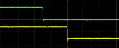
This scope image shows the delay between the interrupt-triggering button push (green) and the LED output inside the ISR (yellow) with the above program running. The timescale is 2us / division, so the response time from external input to ISR output is only about 3 microseconds (with the AVR running at 8 MHz):
THE FINAL PROGRAM – STM32
Once again, the STM32 version of this program is fundamentally the same as the AVR version. What is different is mostly the required interrupt configuration and ISR declaration. Since the STM32 external interrupt capacity is so customizable, it requires more initialization than the AVR. Regarding the ISR declaration, the ARM Cortex M family is rather unique in that it is designed so that regular functions can be ISRs. This is possible because the Cortex M design automatically saves all the status and register data necessary before entering an ISR, and restores it all at the end of the ISR. That is, the Cortex M does automatically all the housekeeping that requires additional ISR code in most other designs. Thus our ISR is just a normal function, without any additional ISR code, which is given the proper name for the EXTI0 interrupt so that it overrides the weak declaration in the startup code. That may be a bit advanced, so just know that it is enough to name the ISR the correct name – I’m sure it’s in the documentation somewhere, but I just looked at the startup files to find the correct name. Being able to look into your compiler startup files is a big advantage, and you should not be afraid to poke around in them.
Also note that, unlike the AVR, the STM32 requires that the interrupt request be explicitly cleared inside the ISR.
// STM32_INT1
// Blink LED on PC9
// Control LED on PC8 via
// button interrupt on PA0
#include <stm32f10x.h>
void EXTI0_IRQHandler(void) // ISR is just a regular function with correct name
{
if (EXTI->RTSR & 1) // was set for positive edge
{
GPIOC->ODR |= (1<<8); // set blue LED
EXTI->RTSR = 0;
EXTI->FTSR = 1; // set for negative edge
}
else // was set for negative edge
{
GPIOC->ODR &= ~(1<<8); // clr blue LED
EXTI->FTSR = 0;
EXTI->RTSR = 1; // set for positive edge
}
EXTI->PR = 1; // clear this interrupt flag
}
void delay(volatile uint32_t d)
{
while (d-- != 0)
;
}
int main(void)
{
RCC->APB2ENR |= RCC_APB2ENR_IOPAEN; // enable PORTA for button input
GPIOA->CRL = (0b0100); // CNF=1, MODE=0 (floating input)
RCC->APB2ENR |= RCC_APB2ENR_IOPCEN; // enable PORTC for LED output
GPIOC->CRH = 0b0010 | (0b0010<<4); // CNF=0, MODE=2 (2MHz output) (PC8,PC9)
AFIO->EXTICR[0] = 0; // EXTI0 is PA0
EXTI->RTSR = 1; // rising edge, EXTI0
EXTI->IMR = 1; // enable EXTI0
NVIC->ISER[0] = (1 << EXTI0_IRQn); // enable EXTI0 in NVIC
while (1)
{
GPIOC->ODR ^= (1<<9); // toggle green LED
delay(80000);
}
}