A PLL is an electronic circuit that produces a replica of its input frequency using a feedback mechanism. Noise in phase locked loops may be due to noise in the oscillator or VCO stages, or due to noise produced by passive and active components.
Noise in PLL
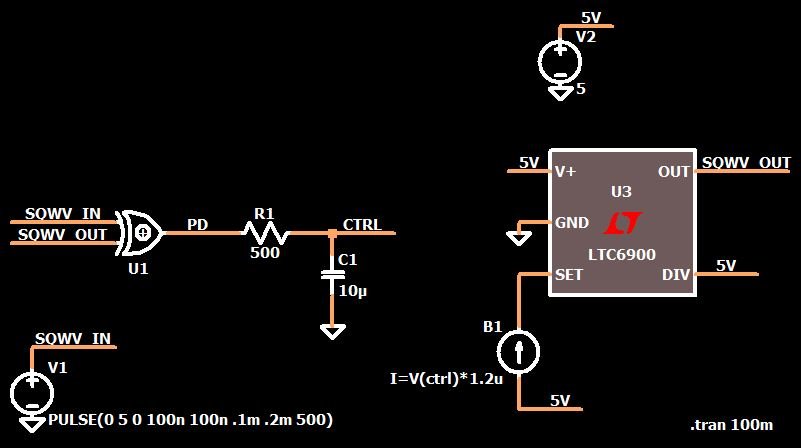
A PLL is an electronic circuit that produces a replica of input frequency using feedback mechanism. It magnifies the frequency or phase error at input. This feedback mechanism continues until it is matched. The signal (having a phase error) is forwarded to VCO to eliminate the phase error to zero. The main parts of a PLL circuit are:
1. Phase detector.
2. Loop filter (LF).
3. Voltage controlled oscillator.
Types of PLL can be categorized by bandwidth and linearity. A PLL can be of wide bandwidth as well as of small bandwidth. Linearity wise, almost all PLLs are non-linear, but they are treated as linear equations when the frequency is matched (locked condition).
Noises in PLL are introduced at different level creating a spectrum of noise. Noise introduced by internal and external sources are:
• Phase Noise.
• Quantization.
• Phase Detector.
• Noise coupled by Tune line.
• Divider.
Behavior of phase noise is not consistent, it is random. It is quite difficult to work out a solution for phase noise. This topic is still an open subject for researchers.
In a well optimized PLL design phase noise is mainly contributed by reference oscillator and VCO. But this doesn’t mean that other hardware is not playing any role. To study how the oscillator causes phase noise in PLL we consider an oscillator generating a nominal frequency f0 in form of sinusoidal waveform. Mathematically we can write it as:
Vout = [A + z(t)]Cos(2pf0t + ?(t)) ……………………………. Eq (i)
A = Amplitude of sinusoidal waveform
Z (t) = Amplitude of noise.
? (t) =Phase difference.
A modern oscillator has an amplitude control mechanism, so the amplitude of phase noise can be neglected. Noise from an external source may also enter and become amplified by the amplifier. This noise may combine with phase noise producing a large noise signal, but normally it is filtered out before entering the input. Filtering is done continuously until the amplifier reaches it saturation. The saturation limit in the amplifier keep its gain in limit.


If we plot the noise spectrum (generated by phase noise, phase detector, noise coupled in tuned line, and noise contributed by divider) it will look like as shown in fig B. The plot shows that noise coupled before the tuned line can be filtered out by a low pass filter. Noise inserted at the tuned line can be minimized by band pass filter and similarly noise introduced at the output of VCO.
There are some other sources that also contribute noise in a PLL. Passive components like resistors cause thermal noise. Similarly active components produce shot noise.
In a good and fully optimized PLL design, other preventive actions that need to be taken to keep the noise at its minimum level are the use of non-saturated logic designs like ECL (Emitter Coupled Logic), TTL (Transistor Transistor Logic), and CMOS


