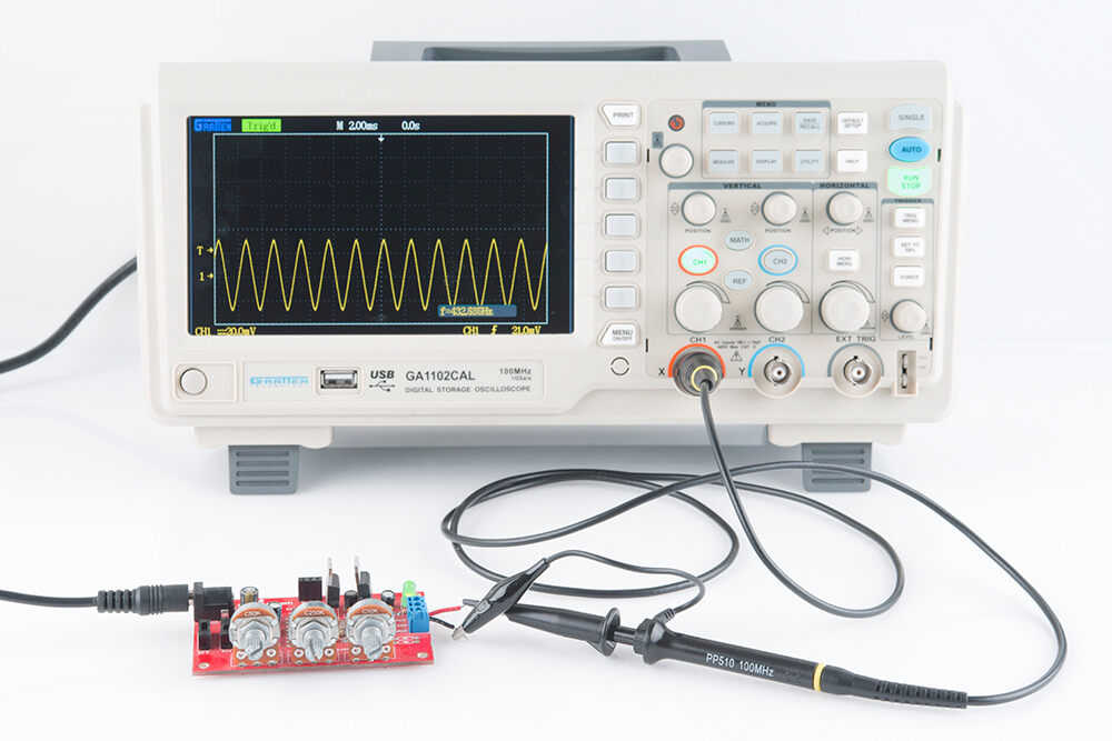
The oscilloscope is an indispensable part in many electrical engineers’ and electric technicians’ toolboxes. The uses of an oscilloscope are as an observational tool, allowing technicians to view signal voltages, which oscillate constantly (hence the name). They are typically fairly small, so as to allow transportation to different locations. Some oscilloscopes designed for laboratory use are larger, especially older models. Meanwhile, the emergence of LCD technology has led to the creation of small, handheld oscilloscope models.

Basic Operations of an Oscilloscope
Oscilloscopes typically consist of four sections. The display is typically the largest part of the device, and can be either an LCD or CRT screen. The screen displays the signal voltage, with vertical and horizontal reference lines. These lines, taken together, are called the graticule. There are three controls for the screen, which are focus, intensity, and beam finder knobs. Besides the screen, there is also a vertical section and a horizontal section, whose operations will be further explained below.
Inputting a Signal
To use an oscilloscope, a technician must input the desired signal to the oscilloscope. To do this, the technician must feed the signal into one of the input connectors. These are most commonly coaxial connectors. Most oscilloscopes have multiple input connectors, allowing users to plot several signals against eachother over time. For signals that don’t have a coaxial connector, users must attach a scope probe to the source. Oscilloscopes generally come with their own scope probes. The input resistance of general use oscilloscopes is one megaohm, which is in parallel with a capacitator of about 20 picofarads.
Basic Operations: The Trace
The trace is one of the most basic operations of an oscilloscope. The oscilloscope draws a trace, which is a horizontal line, across the screen. The timebase control determines how quickly the trace (also called a sweep) is drawn. When the voltage becomes negative or positive, the viewer displays a correspondingly positive or negative jump in the trace on screen.
Vertical and Horizontal Sensitivity Controls
These controls allow the user to determine manually the sensitivity, both vertically and horizontally. This allows oscilloscopes to accommodate a wide range of input amplitudes.
Focus Control
This allows users to adjust the sharpness of the trace. New flatpanel models do this automatically.
Beam Finder
This control prevents the trace from deflecting off screen or otherwise being blocked. Because the beam finder prevents the trace from deflecting off screen, it may temporarily distort the trace.
Timebase Control
This control determines how quickly the oscilloscope draws the trace. This control allows users to manually select the sweep speed, which is in units of seconds per unit on the graticule.
Intensity Control
The intensity control determines how intensely the trace is drawn. For CRT models, a high intensity is desirable for fast traces, and for low speed lower intensity. Speed is unimportant for LCD models.
Types of Sweeps
There are four types of sweeps: triggered, recurrent, single, and delayed. Triggered sweeps reset the screen every time the trace reaches the right end of the screen, and are useful for periodic signals like sine waves. Recurrent and single sweeps are more common on older models, and are less useful for qualitatively observing signals. Delayed sweeps allow users to get a very detailed look at voltage.
Uses of Oscilloscopes
The uses of an oscilloscope are many and varied. The most common use of oscilloscopes is to diagnose electronic equipment malfunctions. Oscilloscopes allow technicians to get a look at what the voltage is doing over time; whether, for example, it is oscillating or not. Technicians can also use oscilloscopes to see the shape and time signals of a signal, which is important in some applications. Technicians can connect to each component independently and from there determine which component is failing.
Oscilloscopes are also used to check electronics. Designers of new equipment typically must run many tests with oscilloscopes to find the location of a particular design flaw. More advanced oscilloscopes have storage capacity to store the signal’s variations over a long period of time, which allows for detailed analysis at a later date.


Comments are closed