Robot builders who are interested in building a mobile robot usually experiment with different types of DC brush motors. Fortunately, they are very easy to test by building simple DC motor circuits. All that is needed is a DC brush motor, battery, and red and black alligator leads.
The Simple DC Motor Circuit
Selecting a Motor for the Simple DC Motor Circuit
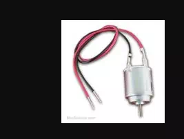
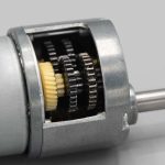
This article will only be dealing with simpler permanent-magnet DC brush motors. More complex motors such as the DC brushless, servo, and stepper motors will not be discussed. In order to determine whether your motor is a DC brushless motor, your motor must have only two wire leads or metal connector terminals. If your motor has more than two connecting wires, it is most likely not a DC brushless motor.
All small-sized double-wire permanent-magnet DC brush motors are essentially the same. Some have wire leads while others have metal connector terminals. Further, some motors have shafts with pulleys or gears attached while others don’t. Nonetheless, all are sufficient for building a simple DC motor circuit.
Selecting a Battery for the Simple DC Motor Circuit
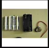
Most small-sized DC brush motors, such as those you would find in toys, are built to operate at 3 V. An ideal power source for your motor would be two AA batteries, together delivering 3 V. However, higher voltage batteries can be used. For instance, a 9 V battery can be connected to a 3 V motor. This connection lasts about 12 seconds before the motor begins to heat up, which you can feel by touching the motor. Therefore, if you’re using a 9 V battery, make sure you allow the motor to cool off for a minute in between every 12 second connection with the 9 V battery. Although 9 V batteries can be used to build a simple DC motor circuit with a 3 V motor, it would be best to use a multimeter to test the 9 V batteries using the voltage setting, and select the battery with a somewhat depleted voltage.
Building the Simple DC Motor Circuit
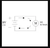
As seen by the figure to the right, the simple DC motor circuit is, as stated by its name, quite simple. In the figure, B1
stands for the 3 V battery and M1 stands for the DC brush motor. To begin building the circuit, take one end of the red alligator lead and connect it to the positive terminal of your battery, while connecting the opposite end of the red alligator lead to the positive terminal of your motor. Afterwards, take one end of the black alligator lead and connect it to the negative terminal of your battery, while connecting the opposite end of the black alligator lead to the negative terminal of the motor. Your motor should now immediately begin to spin.
The Specialized DC Motor Circuit
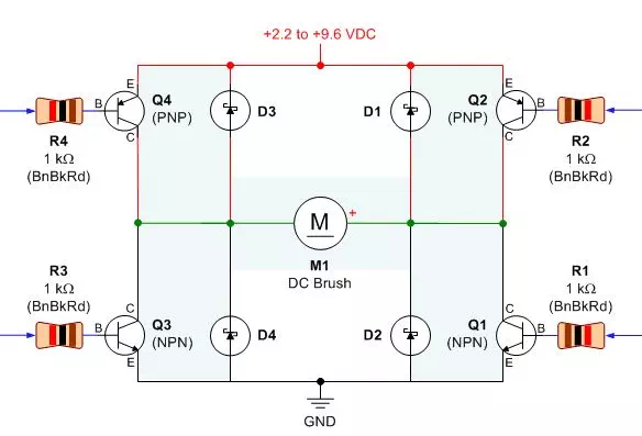
Although the simple DC motor circuit is useful for testing motors, it is not practical when you’re trying to control a motor. Therefore, a unique circuit, called the specialized circuit or motor driver, is used to electronically control the function of DC motors. A common circuit that is used to drive DC motors is the H-bridge. An H-bridge consists of a combination of transistors that allow complete control over a DC motor. The reason that the H-bridge is so commonly used is due to its versatility. It can be used to design a basic circuit, or a more complex circuit that protects the DC motor from damage. Below I have included an example of a simpler H-bridge circuit design.
The different parts of the circuit are as follows:
· Q1 and Q3 are NPN bipolar junction transistors which connect the DC motor to the negative terminal of the battery.
· Q2 and Q4 are PNP bipolar junction transistors which connect the DC motor to the positive terminal of the battery.
· R1-R4 are resistors that control the amount of current that is delivered to the DC motor.
· D1-D4 are diodes that safely allow current to travel back to the battery when the DC motor is made to stop.
· M1 is the DC motor.
All of these various parts work together to allow remote controls to cause a DC motor to spin forwards, spin backwards, slow down, and stop.