Rectification is a process by which an alternating current is made usable for a direct current requirement. Thus, by rectification, alternating current is converted to direct current using equipment known as a rectifier. Learn more about the rectification process and rectifiers in this article.
What is Rectification?
A direct current flows from the positive to negative terminal of a source supply when connected by a circuit. The current flows continuously in a single direction. However, in the case of alternating current, the direction of the flow keeps on changing on the basis of the frequency of the alternator producing it. This means that the current first flows in one direction in the circuit, rises to the peak value and comes down, and then changes the direction, reaches the peak value and again comes back to normal. The rise and fall of the current follows a sine wave pattern and is the characteristic of alternating current.
In a situation wherein direct current is required from a source supplying alternative current, the later needs to be rectified in order to make it usable for the D.C requirement. This process of rectifying the AC current is known as rectification. Thus, rectification can be defined as a process of converting alternating current (A.C) to Direct current (D.C). In this process the flow of current in only one direction is permitted while in the other direction is resisted. This means that in an alternating current (A.C) the positive component of the current is only permitted to pass whereas the negative is resisted. The equipment used for this rectification process is known as rectifier.
In early days, rectification was done using thyristors. However, presently a semi-conductor junction rectifier is used. This modern rectifier is a PN diode which acts as an electrical non return valve when connected to alternating current (A.C) circuit, allowing only current flowing in one direction.
Equipment Used for Rectification Process
The following items of equipment are used in rectifier circuits for assisting in the rectification process.
Transformer
Transformers are attached to the rectifier circuit as they help in bringing the alternating current (A.C) voltage down to the required level. With the help of the transformer, the alternating current (A.C) voltage can be increased or decreased with a small amount of power loss. Moreover, transformers also help in increasing the safety of the equipment being used.
P-N Diodes
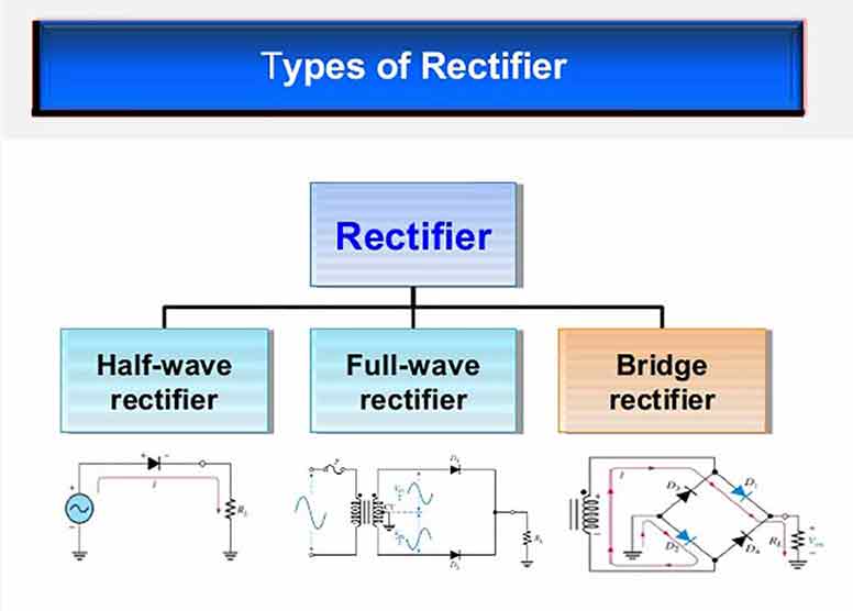
PN diodes are also used for the rectification process along with the transformers. PN diodes help in getting a better rectification of current. The diodes are generally attached in a separate circuit having one, two, or four diodes. The output result is a unidirectional direct current, smooth in quality.
Capacitor
A single rectifier can only produce a half-wave rectification, which though unidirectional, is not continuous in flow and has several ripples in it. In order to reduce these ripples in the direct current, a capacitor is used. Thus, a capacitor helps in smoothing the alternative current (A.C) voltage after the rectification process.
Also, for getting a full wave rectification, two diodes are attached in a circuit. This type of circuit is known as a bridge rectifier. However, in a two diode system, high voltage transformer is needed, which is expensive that the cost of a conventional bridge rectifier.
The number of rectifiers used in a circuit depends on the kind of output required. Higher the number of rectifiers used, better is the quality of rectified output voltage. There are several other methods for the rectification process; however, the above mentioned are the most commonly used ones


