We have been learning about some interesting facts and circuits related to digital electronics such as ghost detection circuit, basic tube-light circuit, DC to DC charger and so forth. Sometimes a circuit might develop some sort of a defect or fault and it is necessary to carry out electrical troubleshooting in such a case. So in this article we will talk about troubleshooting electrical circuits and their components such as control circuit, power circuit etc. You might also be interested to learn about certain related topics such as “How to ebug a Faulty Amplifier” and “Errors in Electrical Measurements”. Let us start by first taking a look at what is meant by troubleshooting.
Troubleshooting is the process of tracing and rectifying faults in electric/electronics circuit. If there is a problem in electric circuit then possible causes may be;
1. Open Circuit – A connection may be broken i.e. open circuited. This fault can be traced with continuity test.
2. Short Circuit – A connection that may be closed is called short circuited. This leads to flow of excessive current in circuit resulting in the damage of components. Short circuit problems are normally caused by weak/damaged insulation which can be detected by insulation test.
To troubleshoot a circuit for fault, all following things should be checked.
· Channel resistance
· Potential difference between two points
· Flow of current
Guide to electrical troubleshooting using schematics and meter
· Check supply input voltage
· Check the voltage at different test points on PCB
· Check all protection devices are operating as they should be
Generally an electrical circuit has two main sections namely as follows:
1. Power circuit
2. Control circuit
Check List for Power Circuit
So first we will check that power supply circuit is properly delivering power. Things that should be checked for power supply circuit are listed below.
· Check input voltage
· Check protection devices are functional
· Check channel resistance
· Check that all the components are physically OK and not damaged by excessive heat
Check List for Control Circuit
· Input voltage to control circuit
· Relays, switches and timers health
· Cable continuity
· Check contact switches are logically operating
· Timing of switching circuit
Continuity Test
Continuity of circuit can be checked by two ways
1. Dead continuity test
2. Power ON continuity test
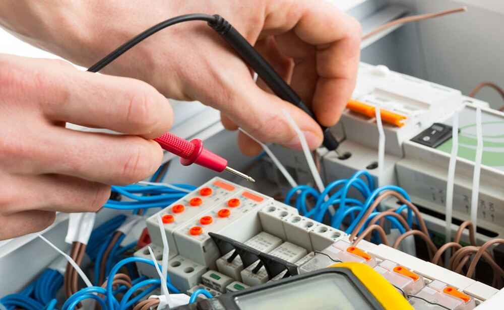
Dead continuity test: The continuity is checked while keeping power off. This reduces the risk of any shock to person performing the test. Similarly insulation test is performed. To check the circuit continuity while power is off, the multi-meter knob is set on beep sound. The beep confirms that electrical path is complete. If path is discontinuous then there will be no beep. Sometime an LED can also be used for visual confirmation


