
We have been reading about rectifier diodes and different rectifier configurations in our previous articles. In this article we will study about a new device known as the Silicon Controlled Rectifier, which is a power electronic device. It can be produced in versions that can handle several thousand Amperes and voltages greater than 1kV. It is a silicon device used for controlled rectification, and hence the reference or nomenclature of Silicon Controlled Rectifier. It can convert alternating current into direct current and at the same time can control the amount of power fed to the load. Thus it combines the features of a rectifier and a transistor.
Why not Germanium Controlled Rectifier?
Leakage current in silicon is very small compared to Germanium. As the device is to be used as a switch, there should be minimum leakage current during the ‘OFF’ condition. Hence Germanium is not popularly used for controlled rectification.
Construction
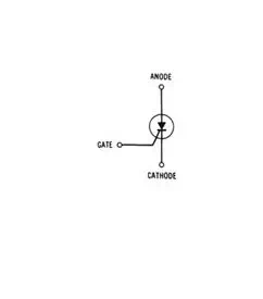
We just now read that SCR is a three terminal device. The terminals are:
· Anode (A)
· Cathode (K)
· Gate (G)
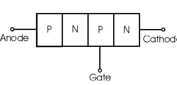
The device consists of three pn junctions to form a p-n-p-n device. The 3 terminals are taken as follows:
· Anode – taken from the outer p-type material
· Cathode – taken from the outer n-type material
· Gate – taken from the inner p-type material
WHY THE NAME ‘THYRISTOR’?
SCR is sometimes called ‘thyristor’ as it is a solid state equivalent of thyratron. The gate, anode and cathode of SCR correspond to grid, plate and cathode of thyratron.
Working of SCR
Important points to be remembered:
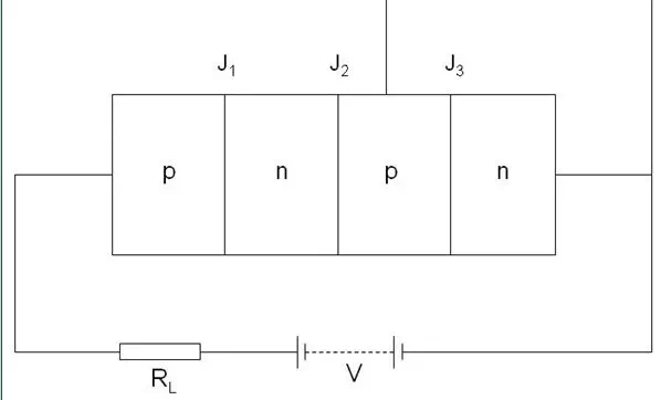
· In SCR, load is connected in series with anode.
· The anode is always kept at a potential higher than the cathode, i.e., A is always at a positive potential with respect to K.
The working of SCR is to be studied under two different conditions:
3. When Gate (G) is open
4. When Gate (G) is positive with respect to Cathode (K)
Here no voltage is applied to the gate. Under this condition, the junction J2 is reverse biased while J1 & J3 are forward biased.
( For example: In junction J1, the p-type material is kept at a positive potential than the n-type material of the pn-junction due to the voltage source connected through the RL. Hence J1 is forward biased.)
Due to the reverse bias, no current will flow through the device => SCR is cut-off.
So can SCR never be turned ON with its gate open?
Yes it can. There is a way to turn ON the SCR with the gate remianing ‘open’.
You can see that the supply voltage V apears as the reverse bias voltage across the junction J2 since J1 & J3 are in forward bias condition (conduct current).When the supply voltage ‘V’ is increased beyond a threshold, breakdown occurs at the junction J2. The SCR now conducts heavily and is in ON state.
This increased voltage at which the SCR conducts heavily without gate voltage is called ‘breakover voltage’.
– When Gate is positive with respect to cathode
The device can be made to conduct heavily by applying a small positive potential to the Gate terminal, as shown in the below fig.
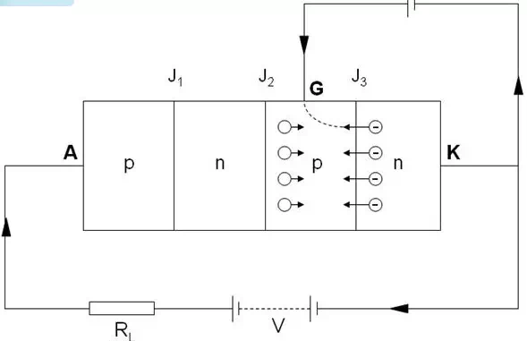
· J3 is forward biased, J2 is reverse biased.
· Electrons from n-type material start moving acoss J3 towards left
· Similarly, holes move from p-type material towards the right.
· Eventually, the electrons that moved across J3 are now attracted across J2. This initiates the Gate current.
· As the J2 is now conducting, anode current flows through the SCR as soon gate current was initiated.
(in layman terms, J2 had been reverse biased – no charge flowed across J2 till now. Now that electrons move across J2, this initiates the current flow through the device)
Note that the Gate is used only to trigger the conduction. As soon as the SCR is triggered, the Gate loses all control as the breakdown of J2 has already been achieved. Hence the anode current does not decrease at all on removing the positive Gate voltage.
The only way to stop conduction is to reduce the applied voltage to zero.
What we infer from the working?
· SCR has two states – either it does not conduct or it conducts heavily. There is no intermediate state. Hence SCR behaves like a switch.
· There are 2 ways to turn ON the SCR – 1. with Gate open and increasing the supply voltage, 2. with a positive Gate trigger. (gate trigger should be >10mA)
· The SCR is turned OFF only by reducing the supply voltage to zero, thereby reducing the anode current <10mA.
This 10mA current is called as Holding current. There are other important terms such as Peak Reverse Voltage, etc which are important to understand the VI-Characteristics of SCR.
Let us discuss about these terms, VI characteristics of SCR and therefore the basic ‘controlled rectification’ application of SCR in the next article.

Comments are closed