VRML, which stands for Virtual Reality Modeling Language, was conceived at the first international conference of the World Wide Web. Mark Pesce, Tony Parisi, and David Ragget outlined the structure of VRML at the conference and specified that it would be a platform – independent language that would be viewed on the Internet. The objective of VRML was to have the capability to put colored objects into a 3D environment.
VRML is an interpreted language, which can be seen as a disadvantage, because it runs slowly on many computers today. However, it has been influential, because it was the first method available for displaying a 3D world on the World Wide Web.
Strictly speaking, VML is not a “tool,” like Premiere or Director. In fact, the only piece of software needed to create VRML content is a text editor. Nonetheless, VRML is a tool used to create 3D environments on the web, much like Flash is a tool used to create interactive movies.
History VRML was conceived in the spring of 1994 at the first annual World Wide Web Conference in Geneva, Switzerland. Tim Berners – Lee and Dave Raggett organized a Birds – of – a – Feather (BOF) session to discuss Virtual Reality interfaces to the World Wide Web. Several BOF attendees described projects already underway to build three dimensional graphical visualization tools which inter – operate with the Web. Attendees agreed on the need for these tools to have a common language for specifying 3D world description and WWW hyper – links — an analog of HTML for virtual reality. The term Virtual Reality Markup Language (VRML) was coined, and the group resolved to begin specification work after the conference. The word ‘Markup’ was later changed to ‘Modeling’ to reflect the graphical nature of VRML.
Shortly after the Geneva BOF session, the www – vrml mailing list was created to discuss the development of a specification for the first version of VRML. The response to the list invitation was overwhelming: within a week, there were over a thousand members. After an initial settling – in period, list moderator Mark Pesce of Labyrinth Group announced his intention to have a draft version of the specification ready by the WWW Fall 1994 conference, a mere five months away. There was general agreement on the list that, while this schedule was aggressive, it was achievable provided that the requirements for the first version were not too ambitious and that VRML could be adapted from an existing solution. The list quickly agreed upon a set of requirements for the first version, and began a search for technologies which could be adapted to fit the needs of VRML.
The search for existing technologies turned up a several worthwhile candidates. After much deliberation the list came to a consensus: the Open Inventor ASCII File Format from Silicon Graphics, Inc. The Inventor File Format supports complete descriptions of 3D worlds with polygonally rendered objects, lighting, materials, ambient properties and realism effects. A subset of the Inventor File Format, with extensions to support networking, forms the basis of VRML. Gavin Bell of Silicon Graphics has adapted the Inventor File Format for VRML, with design input from the mailing list. SGI has publicly stated that the file format is available for use in the open market and have contributed a file format parser into the public domain to bootstrap VRML viewer development.
This is a clarified version of the 1.0 specification. No features have been added or changed from the original 1.0 version of the spec. This is a ‘bug – fix’ release of the spec, correcting misspellings, vague wording and misleading examples, and adding wording to better define the semantics of VRML.
Basic VRML shapes
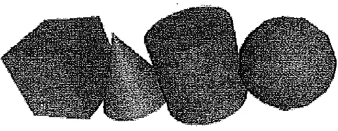
VRML allows for the definition of complex shapes that include Indexed FaceSet and Extrusion. An Indexed FaceSet is a set of faces that make up an object. This allows for the creation of complex shapes, since an arbitrary number of faces is allowed. An Extrusion is a 2D cross – section extruded along a spine and is useful in creating a simple curved surface, such as a flower petal.
An object’s shape, size, color, and reflective properties can be specified in VRML. The Appearance node controls the way a shape looks and can contain a Material node and texture nodes.
A Material node specifies an object’s surface properties. It can control what color the object is by specifying the red, green, and blue values of the object. The specular and emissive colors can be specified similarly. Other attributes, such as how much the object reflects direct and indirect light, can also be controlled. Objects in VRML can be transparent or partially transparent. This is also included in the Material node.
Three kinds of texture nodes can be used to map textures onto any object. The most common one is the Image Texture, which can take an external JPEG or PNG image file and map it onto the shape. The way the image is textured can be specified — that is, the way the image should be tiled onto the object is editable.
A Movie Texture node allows mapping an MPEG movie onto an object; the starting and stopping time can also be specified.
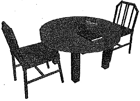
A simple VRML scene
The final texture – mapping node is called a Pixel Texture, which simply means creating an image to use with image Texture VRML. Although it is more inefficient than an ImageTexture node, it is still useful for simple textures.
Text can be put into a VRML world using the Text node. You can specify the text to be included, as well as the font, alignment, and size. By default, the text faces in the positive Y direction, or “up”.
All shapes and text start in the middle of the VRML world. To arrange the shapes, Transform nodes must be wrapped around the shape nodes. The Trans form node can contain Translation, Scale, and Rotation nodes. Translation simply moves the object a specific distance from its current location, which is by default the center of the world. Scale increases or decreases the size of the object, while Rotation rotates the object around its center.
VRML WorldA virtual world needs more than just shapes to be realistic; it needs cameras to view the objects, as well as backgrounds and lighting. The default camera is aligned with the negative z – axis, a few meters from the center of the scene. Using Viewpoint nodes, the default camera position can be changed and other cameras added.
The viewpoint can be specified with the position node and can be rotated from the default view with the orientation node. The camera’s angle for its field of view can be changed from its default 0.78 radians with the f ield Of Viewnode. Changing the field of view can create a teleplioto effect.
Three types of lighting can be used in a VRML world. A Directional Light node shines a light across the whole world in a certain direction, similar to the light from the sun — it is from one direction and affects all objects in the scene. A Point Light shines a light in all directions from a certain point in space. A Spot Light shines a light in a certain direction from a point. Proper lighting is important in adding realism to a world. Many parameters, such as the color and strength of the light, can be specified for every type of light.
The background of the VRML world can also be specified using the Background node. The background color, black by default, as well as the sky color can be changed. A Panorama node can map a texture to the sides of the world. A panorama is mapped onto a large cube surrounding the VRML world. If a panorama is used, the user can never approach the texture, because the panorama is centered on the user. It is also possible to add fog in VRML using the Fog node, where the color and density of the fog can be specified. Fog can increase the frame rate of a world, since objects hidden by the fog are not rendered.
Animation and interactions
An advantage of VRML97 over the original VRML 1.0 is that the VRML world can be interactive. The only method of animation in VRML is tweening, which can be done by slowly changing an object specified in an interpolator node. This node will modify an object over time, based on the type of interpolator.
There are six interpolators: color, coordinate, normal, orientation, position, and scalar. All interpolators have two nodes that must be specified: the key and keyValue. The key consists of a list of two or more numbers, starting with 0 and ending with 1. Each key element must be complemented with a keyValue element. The key defines how far along the animation is, and the keyValue defines what values should change. For example, a key element of 0.5 and its matching key value define what the object should look like at the middle of the animation.
A Time Sensor node times an animation, so that the interpolator knows what stage the object should be in. A Time Sensor has no physical form in the VRML world and just keeps time. To notify an interpolator of a time change, a ROUTE is needed to connect two nodes. One is needed between the Time Sensor and the interpolator and another between the interpolator and the object to be animated. Most animation can be accomplished this way. Chaining ROUTE commands so that one event triggers many others can accomplish complex animations.
Two categories of sensors can be used in VRML to obtain input from a user. The first is environment sensors. There are three kinds of environment sensor nodes: Visibility Sensor, Proximity Sensor, and Collision. A Visibility sensor is activated when a user’s field of view enters an invisible box. A Proximity Sensor is activated when a user enters or leaves an area. A Collision is activated when the user hits the node.
The second category of sensors is called pointing device sensors. The first pointing device sensor is a touch sensor, activated when an object is clicked with the mouse. Three other sensors are called drag sensors. These sensors allow the rotation of spheres, cylinders, and planes when, a mouse is dragging the object.
VRML Specifics
A VRML file is simply a text file with a .wrl extension. VRML97 must include the line #VRML V 2.0 UTF8 in the first line of the file. A # denotes a comment anywhere in the file except for the first line. The first line of a VRML file tells the VRML client what version of VRML to use. VRML nodes are case sensitive and are usually built hierarchically.
Although only a simple text editor such as notepad is needed, VRML – specific text editors are available, such as VRMLpad. They aid in creating VRML objects by providing different colors and collapsing or expanding nodes.
All nodes begin with “{” and end with “}.” and most can contain nodes inside nodes. Special nodes, called group nodes, can cluster multiple nodes. The keyword children followed by “[“begins the list of children nodes, which ends with “]”. A “Transform” node is an example of a group node.
Nodes can be named using DEF and can be used again later by using the keyword USE. This allows for creation of complex objects using many simple objects.
To create a simple box in VRML
Shape {
Geometry Box{} }
The box defaults to a 2 – meter – long cube in the center of the screen. Putting it into a Transform node can move this box to a different part of the scene. We can also give the box a different color, such as red:
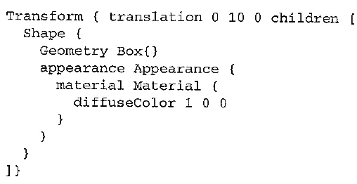
This VRML fragment puts a red box centered in the +10 Y direction. The box can be reused if DEF mybox is put in front of the Transform. Now, whenever the box needs to be used again, simply putting USE mybox will make a copy.