We now have had an introduction to color science and some of the problems that crop up with respect to color for image displays. But how are color models and coordinates systems really used for stored, displayed, and printed images?
RGB Color Model for CRT Displays
We usually store color information directly in RGB form. However, we note from the previous section that such a coordinate system is in fact device – dependent.
We expect to be able to use 8 bits per color channel for color that is accurate enough. In fact, we have to use about 12 bits per channel to avoid an aliasing effect in dark image areas — contour bands that result from gamma correction, since gamma correction results in many fewer available integer levels.
For images produced from computer graphics, we store integers proportional to intensity in the frame buffer. Then we should have a gamma correction LUT between the frame buffer and the CRT. If gamma correction is applied to floats before quantizing to integers, before storage in the frame buffer, then we can use only 8 bits per channel and still avoid contouring artifacts.
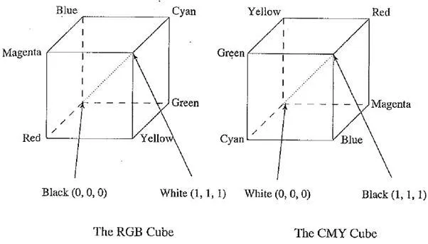
RGB and CMY color cubes. (This figure also appears in the color insert section.)
Subtractive Color: CMY Color Model
So far, we have effectively been dealing only with additive color. Namely, when two light beams impinge on a target, their colors add; when two phosphors on a CRT screen are turned on, their colors add. So, for example, red phosphor + green phosphor makes yellow light.
But for ink deposited on paper, in essence the opposite situation holds: yellow ink subtracts blue from white illumination but reflects red and green; which is why it appears yellow!
So, instead of red, green, and blue primaries, we need primaries that amount to — red, — green, and — blue; we need to subtract R, G, or B. These subtractive color primaries are cyan (C), magenta (M), and yellow (Y) inks. The above figure shows how the two systems, RGB and CMY, are connected. In the additive (RGB) system, black is “no light”, RGB — (0, 0, 0). In the subtractive CMY system, black arises from ^subtracting all the light by laying down inks with C = M = Y = 1.
Transformation from RGB to CMY
Given our identification of the role of inks in subtractive systems, the simplest model we can invent to specify what ink density to lay down on paper, to make a certain desired RGB color, is as follows:
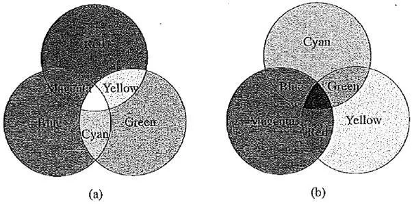
Additive and subtractive color: (a) RGB is used to specify additive color; (b) CMY is ased to specify subtractive color. (This figure also appears in the color insert section.)
Then the inverse transform is
Undercolor Removal: CMYK System
C, M, and Y are supposed to mix to black. However, more often they mix to a muddy brown (we all know this from kindergarten). Truly “black” black ink is in fact cheaper than mixing colored inks to make black, so a simple approach to producing sharper printer colors is to calculate that part of the three – color mix that would be black, remove it from the color proportions, and add it back as real black. This is called “undercolor removal”. The new specification of inks is thus
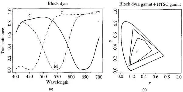
Figure depicts the color combinations that result from combining primary colors available in the two situations: additive color, in which we usually specify color using RGB, and subtractive color, in which we usually specify color using CMY or CMYK.
Printer Gamuts
In a common model of the printing process, printers lay down transparent layers of ink onto a (generally white) substrate. If we wish to have a cyan printing ink truly equal to minus – red,
(a) transmission curves for block dyes; (b) spectrum locus, triangular NTSC gamut, and six – vertex printer gamut
our objective is to produce a cyan ink that completely blocks red light but also completely passes all green and blue light. Unfortunately, such “block dyes” are only approximated in industry. In reality, transmission curves overlap for the C, M, and Y inks. This leads to “crosstalk” between the color channels and difficulties in predicting colors achievable in printing.
The above figure first shows typical transmission curves for real block dyes, and the above second figure shows the resulting color gamut for a color printer that uses such inks. We see that the gamut is smaller than that of an NTSC monitor and can overlap it.
Such a gamut arises from the model used for printer inks. Transmittances are related to optical density D via a logarithm: D = —In T, where T is one of the curves in the above figure (a). A color is formed by a linear combination D of inks, with D a combination of the three densities weighted by weights wi = 1.. 3, and wi can be in the range from zero to the maximum allowable without smearing.
So the overall transmittance T is formed as a product of exponentials of the three weighted densities — light is extinguished exponentially as it travels through a “sandwich” of transparent dyes.
The center of the printer gamut is the white – black axis, and the six boundary vertices correspond to C, M, Y, and the three combinations CM, CY, and MY laid down at full density. Lesser ink densities lie more in the middle of the diagram. Full density for all inks corresponds to the black / white point, which lies in the center of the diagram, at the point marked “o”. For these particular inks, that point has chromaticity (x, y) — (0.276, 0.308).