Video Color Transforms
Methods of dealing with color in digital video derive largely from older analog methods of coding color for TV. Typically, some version of the luminance is combined with color information in a single signal. For example, a matrix transform method called YIQ is used to transmit TV signals in North America and Japan.
This coding also makes its way into VHS videotape coding in these countries, since video tape technologies also use YIQ. In Europe, videotape uses the PAL or SECAM codings, which are based on TV that uses a matrix transform called YUV. Finally, digital video mostly uses a matrix transform called YCbCr that is closely related to YUV.
YUV Color Model
Initially, YUV coding was used for PAL analog video. A version of YUV is now also used in the CCIR 601 standard for digital video.
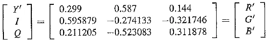
First, it codes a luminance signal (for gamma – corrected signals) equal to. (Recall that Y’ is often called the “luma.”) The luma Y’ is similar to, but not exactly the same as, the CIE luminance value Y, gamma – corrected. In multimedia, practitioners often blur the difference and simply refer to both as the luminance.
As well as magnitude or brightness we need a colorfulness scale, and to this end chrominance refers to the difference between a color and a reference white at the same luminance, It can be represented by the color differences U, V:
We go backward, from (Y’, U, V) to (R’, G’, B’), by inverting the matrix. Note that for a gray pixel, with R’ = G’ = B’, the luminance Y’ is equal to that same gray value, R’, say, since the sum of the coefficients in the equation is 0.299 + 0.587 + 0.114 = 1.0. So for a gray (“black – and – white”) image, the chrominance (U, V) is zero, since the sum of coefficients in each of the lower two equations in (4.28) is zero. Color TV can be displayed on a black – and – white television by just using the Y’ signal. For backward compatibility, color TV uses old black – and – white signals with no color information by identifying the signal with Y’.
Finally, in the actual implementation, U and V are rescaled for purposes of having a more convenient maximum and minimum. For analog video, the scales are chosen such that each of U or V is limited to the range between ±0.5 times the maximum of Y’. (Note that actual voltages are in another, non – normalized range — for analog, Y’ is often in the range 0 to 700 mV, so rescaled U and V, called Pb and PR in that context, range over ±350 mV.)
Such scaling reflects how to deal with component video — three separate signals. How ever, for dealing with composite video, in which we want to compose a single signal out of Y U, and V at once, it rums out to be convenient to contain the composite signal magnitude
within the range —1/3 to ±4/3, so that it will remain within the amplitude limits of the recording equipment. For this purpose, U and V are rescaled as follows:
U = 0.492111(B’-y’)
V = 0.877283(R’ – Y’)
(with multipliers sometimes rounded to three significant digits). Then the chrominance signal is composed from U and V as the composite signal
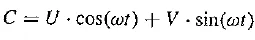
where co represents the NTSC color frequency.
From the above equations we note that zero is not the minimum value for U, V. In terms of real, positive colors, U is approximately from blue (U > 0) to yellow (£/ < 0) in the RGB cube; V is approximately from red (V > 0) to cyan (V < 0).
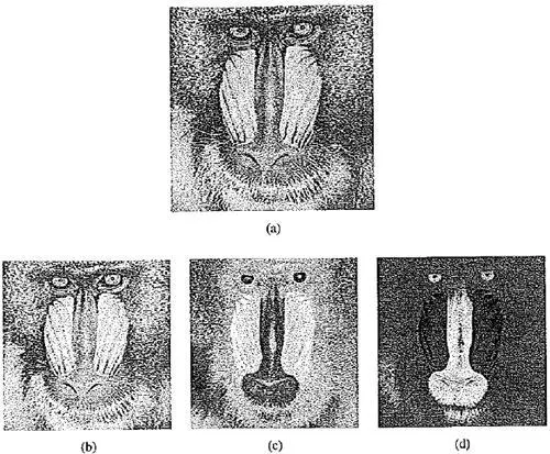
The following figure shows the decomposition of a typical color image into its Y’, U, V components. Since both U and V go negative, the images are in fact shifted, rescaled versions of the actual signals.
Because the eye is most sensitive to black – and – white variations, in terms of spatial frequency (e.g., the eye can see a grid of fine gray lines more clearly than fine colored lines), in the analog PAL signal a bandwidth of only 1.3 MHz is allocated to each of U and V, while 5.5 MHz is reserved for the Y’ signal. In fact, color information transmitted for color TV is actually very blocky.
YIQ Color Model
YIQis the color space used by the NTSC color TV system, employed mainly in North and Central America, and Japan. It is currently in use only for low – power television stations, as full – power analog transmission was ended by the U.S. Federal Communications Commission (FCC) on 12 June 2009. It is still federally mandated for these transmissions as shown in this excerpt of the current FCC rules and regulations part 73 “TV transmission standard”
It is thought that, although U and V are more simply defined, they do not capture the most – to – least hierarchy of human vision sensitivity. Although they nicely define the color differences, they do not best correspond to actual human perceptual color sensitivities. NTSC uses I and Q instead.
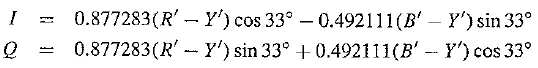
YIQ is just a version of YUV, with the same Y1 but with U and V rotated by 33°:
Y’XJV decomposition of color image: (a) original color image; (b) Y’ (c) £/; (d) V. (This figure also appears in the color insert section.)
This leads to the following matrix transform:
I is roughly the orange – blue direction, and Q roughly corresponds to the purple – green direction.
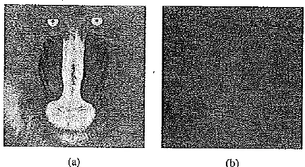
The following figure shows the decomposition of the same color image as above into YIQ components. Only the / and Q components are shown, since the original image and the Y’ component are the same.
For this particular image, most of the energy is captured in the Y’ component, which is typical. However, in this case the YIQ decomposition does a better of job of forming a hierarchical sequence of images: for the 8 – bit Y’ component, the root – mean – square (RMS) value is 137 (with 255 the maximum possible). The U, V components have RMS values 43 and 44. For the YIQ decomposition, the / and Q components have RMS values 42 and 14, so they better prioritize color values. Originally, NTSC allocated 4.2 MHz to Y, 1.5 MHz to I, and 0.6 MHz to Q. Today, both / and Q are each allocated 1.0 MHz.
(a) I and (b) Q components of color image
YCbCr Color Model
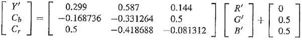
The international standard for component (three – signal, studio quality) digital video is officially Recommendation ITU – R BT.601 – 4 (ioiown as “Rec. 601”). This standard uses another color space, YCbCr, often simply written YCbCr. The YCbCr transform is used in JPEG image compression and MPEG video compression and is closely related to the YUV transform. YUV is changed by scaling such that Q, is U, but with a coefficient of 0.5 multiplying B’. In some software systems, Q, and Cr are also shifted such that values are between 0 and 1. This makes the equations as follows:
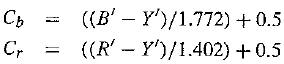
written out, we then have
In practice, however, Rec. 601 specifies 8 – bit coding, with a maximum Y’ value of only 219 and a minimum of +16. Values below 16 and above 235, denoted headroom and footroom, are reserved for other processing. Cb and Cr have a range of ±112 and offset of +128 (in other words, a maximum of 240 and a minimum of 16). If R’, G’, B’ are floats in [0.. + 1], we obtain Y’, Cb, Cr in [0.. 255] via the transform
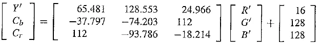
In fact, the output range is also clamped to [1..254], since the Rec. 601 synchronization signals are given by codes 0 and 255.