Analog video is a video signal transferred by an analog signal. When combined in to one channel, it is called composite video as is the case, among others with NTSC, PAL and SECAM.
Analog video may be carried in separate channels, as in two channel S – Video (YC) and multi – channel component video formats.
Analog video is used in both consumer and professional television production applications. However, digital video signal formats with higher quality have been adopted, including serial digital interface (SDI), Firewire (IEEE 1394), Digital Visual Interface (DVI) and High – Definition Multimedia Interface (HDMI).
Most TV is still sent and received as an analog signal. Once the electrical signal is received, we may assume that brightness is at least a monotonic function of voltage, if not necessarily linear, because of gamma correction.
An analog signal f(t) samples a time – varying image. So – called progressive scanning traces through a complete picture (a frame) row – wise for each time interval. A high – resolution computer monitor typically uses a time interval of 1/72 second.
In TV and in some monitors and multimedia standards, another system, interlaced scanning, is used. Here, the odd – numbered lines are traced first, then the even – numbered lines. This results in “odd” and “even” fields — two fields make up one frame.
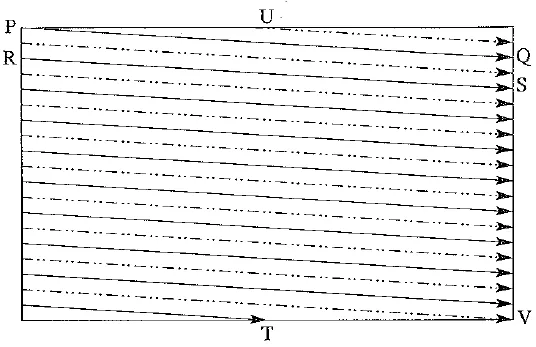
In fact, the odd lines (starting from 1) end up at the middle of a line at the end of the odd field, and the even scan starts at a half – way point. The following figure shows the scheme used. First the solid (odd) lines are traced— P to Q, then R to S, and so on, ending at T — then the even field starts at U and ends at V. The scan fines are not horizontal because a small voltage is applied, moving the electron beam down over time.
Interlaced raster scan
Interlacing was invented because, when standards were being defined, it was difficult to transmit the amount of information in a full frame quickly enough to avoid flicker. The double number of fields presented to the eye reduces perceived flicker.
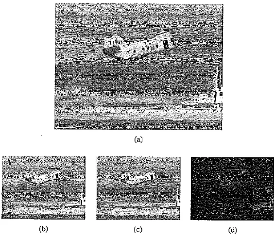
Because of interlacing, the odd and even lines are displaced in time from each other. This is generally not noticeable except when fast action is taking place onscreen, when blurring may occur. For example, in the video in the following figure, the moving helicopter is blurred more than the still background.
Since it is sometimes necessary to change the frame rate, resize, or even produce stills from an interlaced source video, various schemes are used to de – interlace it. The simplest de – interlacing method consists of discarding one field and duplicating the scan lines of the other field, which results in the information in one field being lost completely. Other, more complicated methods retain information from both fields.
CRT displays are built like fluorescent lights and must flash 50 to 70 times per second to appear smooth. In Europe, this fact is conveniently tied to their 50 Hz electrical system, and they use video digitized at 25 frames per second (fps); in North America, the 60 Hz electric system dictates 30 fps.
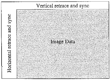
The jump from Q to R and so on is called the horizontal retrace, during which the electronic beam in the CRT is blanked. The jump from T to U or V to P is called the vertical retrace.
Interlaced scan produces two fields for each frame:(a) the video frame; (b) Field 1; (c) Field 2; (d) difference of Fields
Since voltage is one – dimensional — it is simply a signal that varies with time — how do we know when a new video line begins? That is, what part of an electrical signal tells us that we have to restart at the left side of the screen?
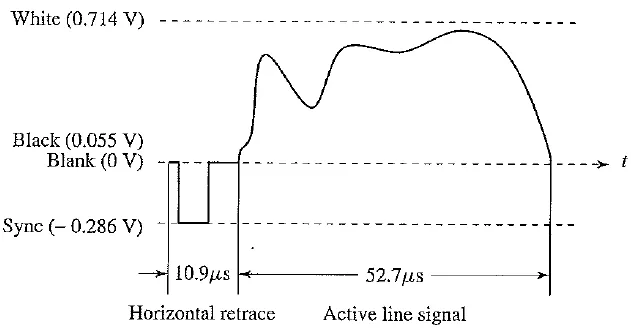
The solution used in analog video is a small voltage offset from zero to indicate black and another value, such as zero, to indicate the start of a line. Namely, we could use a “blacker – than – black” zero signal to indicate the beginning of a line.
The following figure shows a typical electronic signal for one scan line of NTSC composite video. ‘White’ has a peak value of 0.714 V; ‘Black’ is slightly above zero at 0.055 V; whereas
Blank is at zero volts. As shown, the time duration for blanking pulses in the signal is used for synchronization as well, with the tip of the Sync signal at approximately — 0.286 V. In fact, the problem of reliable synchronization is so important that special signals to control sync take up about 30% of the signal!
Electronic signal for one NTSC scan line
The vertical retrace and sync ideas are similar to the horizontal one, except that they happen only once per field.
NTSC Video
NTSC, named for the National Television System Committee, is the analog television system that is used in most of North America, parts of South America (except Brazil, Argentina, Uruguay, and French Guiana), Myanmar, South Korea, Taiwan, Japan, the Philippines, and some Pacific island nations and territories.
Most countries using the NTSC standard, as well as those using other analog television standards, are switching to newer digital television standards, of which at least four different ones are in use around the world. North America, parts of Central America, and South Korea are adopting the ATSC standards, while other countries are adopting or have adopted other standards.
The first NTSC standard was developed in 1941 and had no provision for color television. In 1953 a second modified version of the NTSC standard was adopted, which allowed color television broadcasting compatible with the existing stock of black – and – white receivers. NTSC was the first widely adopted broadcast color system and remained dominant where it had been adopted until the first decade of the 21st century, when it was replaced with digital ATSC. After nearly 70 years of use, the vast majority of over – the – air NTSC transmissions in the United States were turned off on June 12, 2009 and August 31, 2011 in Canada and most other NTSC markets.
Digital broadcasting permits higher – resolution television, but digital standard definition television in these countries continues to use the frame rate and number of lines of resolution established by the analog NTSC standard; systems using the NTSC frame rate and resolution (such as DVDs) are still referred to informally as “NTSC”. NTSC baseband video signals are also still often used in video playback (typically of recordings from existing libraries using existing equipment) and in CCTV and surveillance video systems.
Video raster, including retrace and sync data
Samples per line for various analog video formats
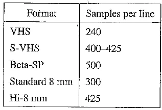
Different video formats provide different numbers of samples per line, as listed in the above table. Laser disks have about the same resolution as Hi – 8. (In comparison, mini DV 1/4 – inch tapes for digital video are 480 lines by 720 samples per line.)
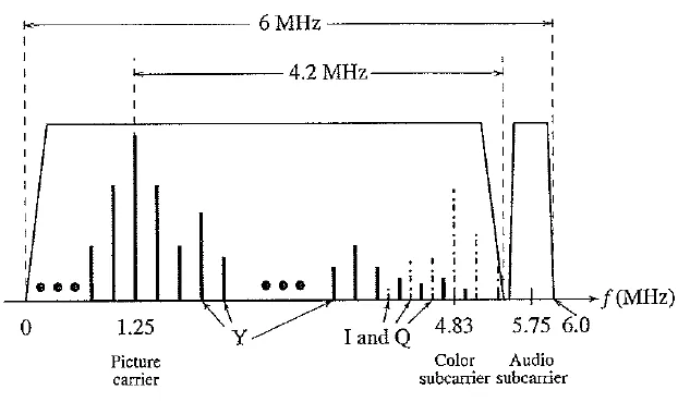
Interleaving Y and C signals in the NTSC spectrum
PAL Video
PAL (Phase Alternating Line) is a TV standard originally invented by German scientists. It uses 625 scan lines per frame, at 25 frames per second (or 40 msec / frame), with a 4 : 3 aspect ratio and interlaced fields. Its broadcast TV signals are also used in composite video. This important standard is widely used in Western Europe, China, India and many other parts of the world.
PAL uses the YUV color model with an 8 MHz channel, allocating a bandwidth of 5.5 MHz to Y and 1.8 MHz each to U and V. The color subcarrier frequency is fsc ≈ 4.43 MHz. To improve picture quality, chroma signals have alternate signs (e.g., +U and — U) in successive scan lines; hence the name “Phase Alternating Line. This facilitates the use of a (line – rate) comb filter at the receiver — the signals in consecutive lines are averaged so as to cancel the chroma signals (which always carry opposite signs) for separating Y and C and obtain high – quality Y signals.
SECAM Video
SECAM, which was invented by the French, is the third major broadcast TV standard. SECAM stands for Systeme Electronique Couleur Avec Memorie. SECAM also uses 625 scan lines per frame, at 25 frames per second, with a 4:3 aspect ratio and interlaced fields. The original design called for a higher number of scan lines (over 800), but the final version settled for 625.
SECAM and PAL are similar, differeing slightly in their color coding scheme. In SECAM, U and V signals are modulated using separate color subcarriers at 4.25 MHz and 4.41 MHz, respectively. They are sent in alternate lines – that is, only one of the U or V signals will be sent on each scan line.