
Digital video comprises a series of orthogonal bitmap digital images displayed in rapid succession at a constant rate. In the context of video these images are called frames. We measure the rate at which frames are displayed in frames per second (FPS).
Since every frame is an orthogonal bitmap digital image it comprises a raster of pixels. If it has a width of W pixels and a height of Hpixels we say that the frame size is WxH.
Pixels have only one property, their color. The color of a pixel is represented by a fixed number of bits. The more bits the more subtle variations of colors can be reproduced. This is called the color depth (CD) of the video.
An example video can have a duration (T) of 1 hour (3600sec), a frame size of 640 x 480 (W x H) at a color depth of 24bits and a frame rate of 25fps. This example video has the following properties:
· pixels per frame = 640 * 480 = 307,200
· bits per frame = 307,200 * 24 = 7,372,800 = 7.37Mbits
· bit rate (BR) = 7.37 * 25 = 184.25Mbits / sec
· video size (VS) = 184Mbits / sec * 3600sec = 662,400Mbits = 82,800Mbytes = 82.8Gbytes
The advantages of digital representation for video are many. It permits
· Storing video on digital devices or in memory, ready to be processed (noise removal, cut and paste, and so on) and integrated into various multimedia applications
· Direct access, which makes nonlinear video editing simple Repeated recording without degradation of image quality
· Ease of encryption and better tolerance to channel noise
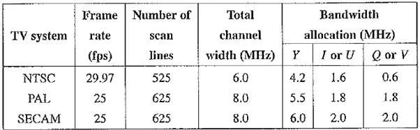
Table Comparison of analog broadcast TV systems
In earlier Sony or Panasonic recorders, digital video was in the form of composite video. Modem digital video generally uses component video, although RGB signals are first converted into a certain type of color opponent space, such as YUV. The usual color space is YCbCr.
Chroma Subsampling
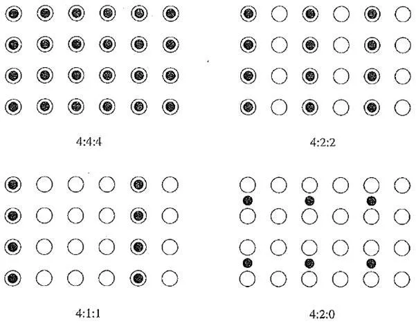
Since humans see color with much less spatial resolution than black and white, it makes sense to decimate the chrominance signal. Interesting but not necessarily informative names have arisen to label the different schemes used. To begin with, numbers are given stating how many pixel values, per four original pixels, are actually sent. Thus the chroma subsampling scheme “4:4:4” indicates that no chroma subsampling is used. Each pixel’s Y, Cb, and Cr values are transmitted, four for each of Y, Cb, and Cr.
The scheme “4:2:2” indicates horizontal subsampling of the Cb and Cr signals by a factor of 2. That is, of four pixels horizontally labeled 0 to 3, all four 7s are sent, and every two Cbs and two Crs are sent, as {CbO, Y0)(Cr0, Yl)(Cb2, Y2)(Cr2, Y3)(Cb4, Y4), and so on.
The scheme “4:1:1” subsamples horizontally by a factor of 4. The scheme “4:2:0” subsamples in both the horizontal and vertical dimensions by a factor of 2. Theoretically, an average chroma pixel is positioned between the rows and columns, as shown in the below figure. We can see that the scheme 4:2:0 is in fact another kind of 4:1:1 sampling, in the sense that we send 4, 1, and 1 values per 4 pixels. Therefore, the labeling scheme is not a very reliable mnemonic!
Scheme 4:2:0, along with others, is commonly used in JPEG and MPEG.
CCIR Standards for Digital Video
The CCIR is the Consultative Committee for International Radio. One of the most important standards it has produced is CCIR – 601, for component digital video. This standard has since become standard ITU – R – 601, an international standard for professional video applications. It is adopted by certain digital video formats, including the popular DV video.
The NTSC version has 525 scan fines, each having 858 pixels (with 720 of them visible, not in the blanking period).Because the NTSC version uses 4:2:2, each pixel can be
Chroma subsampling
represented with two bytes (8 bits for Y and 8 bits alternating between Cb and Cr). The CCIR 601. (NTSC) data rate (including blanking and sync but excluding audio) is thus approximately 216 Mbps (megabits per second):
525 x 858 x 30 x 2 bytes x 8 bits / byte≈ 216 Mbps
During blanking, digital video systems may make use of the extra data capacity to carry audio signals, translations into foreign languages, or error – correction information.
The following table shows some of the digital video specifications, all with an aspect ratio of 4:3. The CCIR 601 standard uses an interlaced scan, so each field has only half as much vertical resolution (e.g., 240 lines in NTSC).
Table Digital video specifications
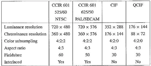
CIF stands for Common Intermediate Format, specified by the International Telegraph and Telephone Consultative Committee (CCITT), now superseded by the International Telecommunication Union, which oversees both telecommunications (ITU – T) and radio frequency matters (ITU – R) under one United Nations body. The idea of CIF, which is about the same as VHS quality, is to specify a format for lower bitrate. CIF uses a progressive (noninterlaced) scan. QCIF stands for Quarter – CIF, and is for even lower bitrate. All the CIF / QCIF resolutions are evenly divisible by 8, and all except 88 are divisible by 16; this is convenient for block – based video coding in H.261 and H.263.
CIF is a compromise between NTSC and PAL, in that it adopts the NTSC frame rate and half the number of active lines in PAL. When played on existing TV sets, NTSC TV will first need to convert the number of lines, whereas PAL TV will require frame-rate conversion.
High Definition TV (HDTV)
The introduction of wide – screen movies brought the discovery that viewers seated near the screen enjoyed a level of participation (sensation of immersion) not experienced with conventional movies. Apparently the exposure to a greater field of view, especially the involvement of peripheral vision, contributes to the sense of “being there”. The main thrust of High Definition TV (HDTV) is not to increase the “definition” in each unit area, but rather to increase the visual field, especially its width.
First – generation HDTV was based on an analog technology developed by Sony and NHK in Japan in the late 1970s. HDTV successfully broadcast the 1984 Los Angeles Olympic Games in Japan. Multiple sub – Nyquist Sampling Encoding (MUSE) was an improved NHK HDTV with hybrid analog / digital technologies that was put in use in the 1990s. It has 1,125 scan lines, interlaced (60 fields per second), and a 16:9 aspect ratio. It uses satellite to broadcast — quite appropriate for Japan, which can be covered with one or two satellites.
The Direct Broadcast Satellite (DBS) channels used have a bandwidth of 24 MHz. In general, terrestrial broadcast, satellite broadcast, cable, and broadband networks are all feasible means for transmitting HDTV as well as conventional TV. Since uncompressed
Table Advanced Digital TV Formats Supported by ATSC
HDTV will easily demand more than 20 MHz bandwidth, which will not fit in the current 6 MHz or 8 MHz channels, various compression techniques are being investigated. It is also anticipated that high – quality HDTV signals will be transmitted using more than one channel, even after compression.
In 1987, the FCC decided that HDTV standards must be compatible with the existing NTSC standard and must be confined to the existing Very High Frequency (VHF) and Ultra High Frequency (UHF) bands. This prompted a number of proposals in North America by the end of 1988, all of them analog or mixed analog / digital.
In 1990, the FCC announced a different initiative — its preference for full – resolution HDTV. They decided that HDTV would be simultaneously broadcast with existing NTSC TV and eventually replace it. The development of digital HDTV immediately took off in North America.
Witnessing a boom of proposals for digital HDTV, the FCC made a key decision to go all digital in 1993. A “grand alliance” was formed that included four main proposals, by General Instruments, MIT, Zenith, and AT&T, and by Thomson, Philips, Sarnoff and others. This eventually led to the formation of the Advanced Television Systems Committee (ATSC), which was responsible for the standard for TV broadcasting of HDTV. In 1995, the U.S. FCC Advisory Committee on Advanced Television Service recommended that the ATSC digital television standard be adopted.
The standard supports video scanning formats shown in Table. In the table, “I” means interlaced scan and “P” means progressive (noninterlaced) scan. The frame rates supported are both integer rates and the NTSC rates — that is, 60.00 or 59.94, 30.00 or 29.97, 24.00 or 23.98 fps.
For video, MPEG – 2 is chosen as the compression standard. As will be seen in Chapter, it uses Main Level to High Level of the Main Profile of MPEG – 2. For audio, AC – 3 is the standard. It supports the so – called 5.1 channel Dolby surround sound — five surround channels plus a subwoofer channel.
The salient difference between conventional TV and HDTV [4, 6] is that the latter has a much wider aspect ratio of 16:9 instead of 4:3. (Actually, it works out to be exactly one – third wider than current TV) Another feature of HDTV is its move toward progressive (noninterlaced) scan. The rationale is that interlacing introduces serrated edges to moving objects and flickers along horizontal edges.
The FCC has planned to replace all analog broadcast services with digital TV broadcasting by the year 2006. Consumers with analog TV sets will still be able to receive signals via an 8 – VSB (8 – level vestigial sideband) demodulation box. The services provided will include
· Standard Definition TV (SDTV)— the current NTSC TV or higher
· Enhanced Definition TV (EDTV) — 480 active lines or higher — the third and fourth rows
· High Definition TV (HDTV)— 720 active lines or higher. So far, the popular choices are 720P (720 lines, progressive, 30 fps) and 10801 (1,080 lines, interlaced, 30 fps or 60 fields per second). The latter provides slightly better picture quality but requires much higher bandwidth.