Mesh Current Analysis is a technique used to find the currents circulating around a loop or mesh with in any closed path of a circuit.
While Kirchhoff´s Laws give us the basic method for analysing any complex electrical circuit, there are different ways of improving upon this method by using Mesh Current Analysis or Nodal Voltage Analysis that results in a lessening of the math’s involved and when large networks are involved this reduction in maths can be a big advantage.
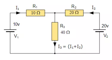
For example, consider the electrical circuit example from the previous section.
Mesh Current Analysis Circuit
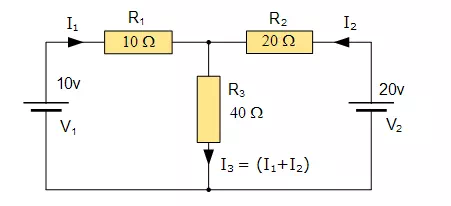
One simple method of reducing the amount of math’s involved is to analyse the circuit using Kirchhoff’s Current Law equations to determine the currents, I1 and I2 flowing in the two resistors. Then there is no need to calculate the current I3 as its just the sum of I1 and I2. So Kirchhoff’s second voltage law simply becomes:
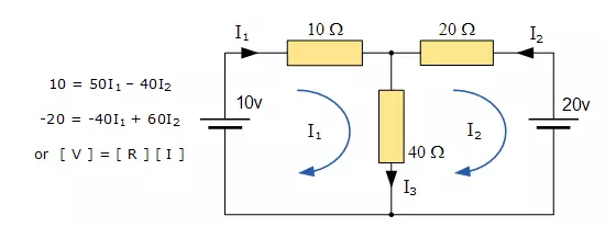
· Equation No 1 : 10 = 50I1 + 40I2
· Equation No 2 : 20 = 40I1 + 60I2
therefore, one line of math’s calculation have been saved.
Mesh Current Analysis
An easier method of solving the above circuit is by using Mesh Current Analysis or Loop Analysis which is also sometimes called Maxwell´s Circulating Currents method. Instead of labelling the branch currents we need to label each “closed loop” with a circulating current. As a general rule of thumb, only label inside loops in a clockwise direction with circulating currents as the aim is to cover all the elements of the circuit at least once. Any required branch current may be found from the appropriate loop or mesh currents as before using Kirchhoff´s method.
For example: : i1 = I1 , i2 = -I2 and I3 = I1 – I2
We now write Kirchhoff’s voltage law equation in the same way as before to solve them but the advantage of this method is that it ensures that the information obtained from the circuit equations is the minimum required to solve the circuit as the information is more general and can easily be put into a matrix form.
For example, consider the circuit from the previous section.
These equations can be solved quite quickly by using a single mesh impedance matrix Z. Each element ON the principal diagonal will be “positive” and is the total impedance of each mesh. Where as, each element OFF the principal diagonal will either be “zero” or “negative” and represents the circuit element connecting all the appropriate meshes. First we need to understand that when dealing with matrices, for the division of two matrices it is the same as multiplying one matrix by the inverse of the other as shown.
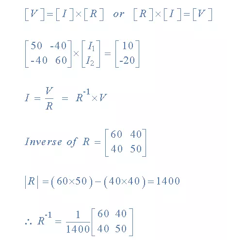
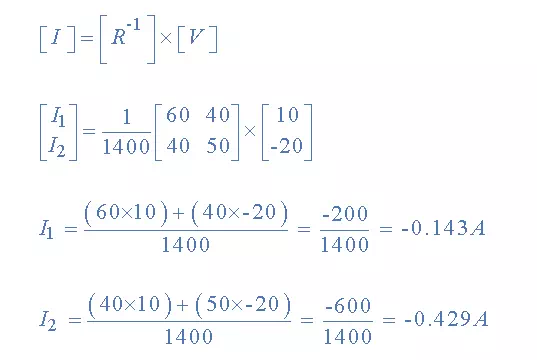
having found the inverse of R, as V/R is the same as V x R-1, we can now use it to find the two circulating currents.
Where:
· [ V ] gives the total battery voltage for loop 1 and then loop 2
· [ I ] states the names of the loop currents which we are trying to find
· [ R ] is the resistance matrix
· [ R-1 ] is the inverse of the [ R ] matrix
and this gives I1 as -0.143 Amps and I2 as -0.429 Amps
As : I3 = I1 – I2
The combined current of I3 is therefore given as : -0.143 – (-0.429) = 0.286 Amps
which is the same value of 0.286 amps, we found using Kirchoff´s circuit law in the previous tutorial.
Mesh Current Analysis Summary
This “look-see” method of circuit analysis is probably the best of all the circuit analysis methods with the basic procedure for solving Mesh Current Analysis equations is as follows:
· 1. Label all the internal loops with circulating currents. (I1, I2, …IL etc)
· 2. Write the [ L x 1 ] column matrix [ V ] giving the sum of all voltage sources in each loop.
· 3. Write the [ L x L ] matrix, [ R ] for all the resistances in the circuit as follows:
·
o R11 = the total resistance in the first loop.
o Rnn = the total resistance in the Nth loop.
o RJK = the resistance which directly joins loop J to Loop K.
· 4. Write the matrix or vector equation [V] = [R] x [I] where [I] is the list of currents to be found.
As well as using Mesh Current Analysis, we can also use node analysis to calculate the voltages around the loops, again reducing the amount of mathematics required using just Kirchoff’s laws. In the next tutorial relating to DC circuit theory, we will look at Nodal Voltage Analysis to do just that.
MESH ANALYSIS:
This is an alternative structured approach to solving the circuit and is based on calculating mesh currents. A similar approach to the node situation is used. A set of equations (based on KVL for each mesh) is formed and the equations are solved for unknown values. As many equations are needed as unknown mesh currents exist.
Step 1: Identify the mesh currents
Step 2: Determine which mesh currents are known
Step 3: Write equation for each mesh using KVL and that includes the mesh currents Step 3: Solve the equations
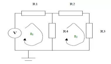
Step 1:
The mesh currents are as shown in the diagram on the next page
Step 2:
Neither of the mesh currents is known
Step 3:
KVL can be applied to the left hand side loop. This states the voltages around the loop sum to zero.
When writing down the voltages across each resistor equations are the mesh currents.
I1R1 + (I1 – I2) R4 – V = 0
KVL can be applied to the right hand side loop. This states the voltages around the loop sum to
zero. When writing down the voltages across ea the equations are the mesh currents.
I2R2 + I2R3 + (I2 – I1) R4 = 0
Step 4:
Solving the equations we get
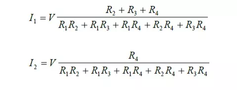
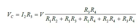
The individual branch currents can be obtained from the these mesh currents and the node voltages can also be calculated using this information. For example:
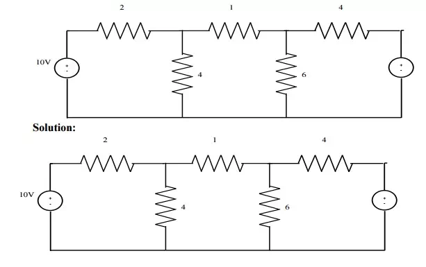
Problem 1:
Use mesh-current analysis to determine the current flowing in (a the 1Ω resistance of the d.c. circuit shown in
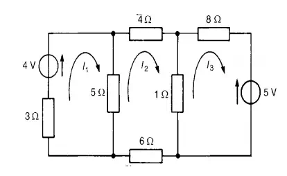
The mesh currents I1, I2 and I3 are shown in Figure
Using Kirchhoff’s voltage law:
For loop 1, (3 + 5) I1 −I2 = 4 …………………………………………………………(1)
For loop 2, (4 + 1 + 6 + 5) I2 −(5) I1 −(1) I3 = 0…………………………………….(2)
For loop 3, (1 + 8) I3 −(1) I2 = 5− ……………………………………………………(3)
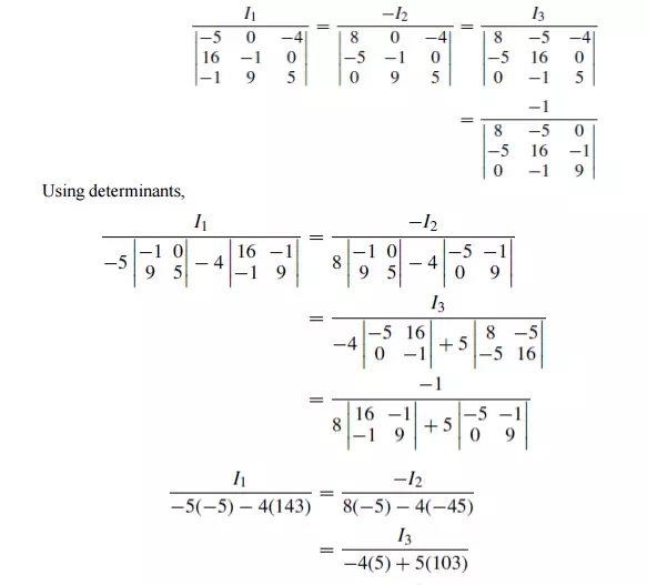
Thus
8I1 −5I2 −4 =0
−5I1 + 16I2 −I3 =0
−I2 + 9I3 + 5 =0
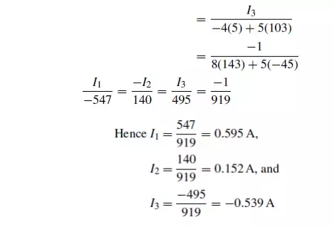
(a) Current in the 5 Ωresistance = I1 −I2
= 0.595 −0.152
= 0.44A
(b) Current in the 1 Ωresistance = I2 −I3
= 0.152 −(−0.539)
= 0.69A
Problem 2: For the a.c. network shown in Figure determine, using mesh-current analysis, (a) themesh currents I1 and I2 (b) the current flowing in the capacitor, and (c) the active power delivered by the 100∠0◦V voltage source.
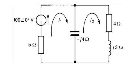
(a) For the first loop
(5−j4) I1 −(−j4I2) =100∠0◦……………………………………………………(1) For the second loop
(4+j3−j4)I2 −(−j4I1) =0 ……………………………………………………… (2)
Rewriting equations (1) and (2) gives:
(5 −j4)I1 + j4I2 −100 =0
j4I1 + (4 −j) I2 + 0 =0 Thus, using determinants,
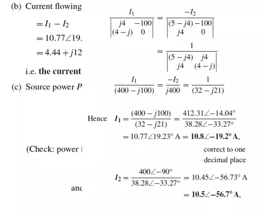
Thus total power dissipated = 579.97 + 436.81 = 1016.8W = 1020W
Problem 3: Calculate current through-6Ω resistance u
Case(1): Consider loop ABGH ; Apply KVL .
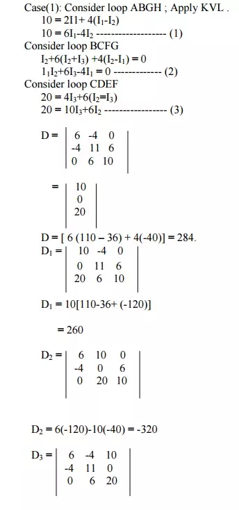
D3 = 6(220) +4(-80) +10(-24)
D3 = 760
I1 = D1/D = 260/284 = 0.915A
I2 = D2/D = -320/284 = -1.1267A I3 = D3/D = 760/284 = 2.676A
Current through 6Ω 2 +Iresistance3 = I
= -1.1267+2.676 = 1.55A