
Network reduction: voltage and current division, source transformation –star delta conversion. Thevenins and Novton & Theorem –Superposition Theorem –Maximum power transfer theorem – Reciprocity Theorem.
3 POTENTIAL DIVIDER:
The circuit shown in Figure (b) is often referred to as a potential divider circuit. Such a circuit can consist of a number of similar elements in series connected across a voltage source, voltages being taken from connections between the elements. Frequently the divider consists of two resistors as shown in Figure (b), where
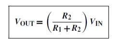
A potential divider is the simplest way of producing a source of lower e.m.f. from a source of higher e.m.f., and is the basic operating mechanism of the potentiometer, a measuring device for accurately measuring potential differences
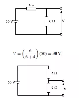
Problem 1: Determine the value of voltage V shown in Figure
Problem 2: Two resistors are connected in series across a 24V supply and a current of 3A flows in the circuit. If one of the resistors has resis and (b) the p.d. across the 2 Ωresistor. If the circuit is connected for 50 hours, how much energy is used?
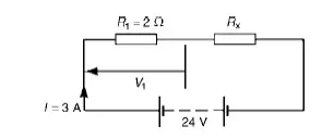
(a) Total circuit resistance R= V/ I
= 24/3=8 Ω Value of unknown resistance, Rx =8 −2=6 Ω
(b) P.d. across 2 Ωresistor, V1 =IR1 =3 × 2=6V Alternatively, from above,
V1 = (R1/R1 + Rx)) V = (2/2 + 6) (24) = 6V Energy used = power × time
= V × I × t
= (24 × 3W) (50 h)
= 3600Wh = 3.6kWh
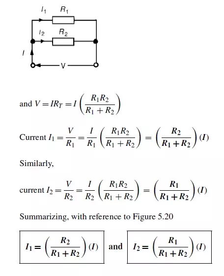
Current division:
For the circuit shown in Figure, the total circuit resistance, RT is given by:
RT = R1R2/R1 + R2
Problem 1: For the series-parallel arrangement shown in Figure, find (a) the supply current, (b) thecurrent flowing through each resistor and (c) the p.d. across each resistor.
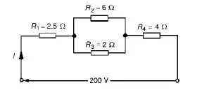
(a) The equivalent resistance Rx of R2 and R3 in parallel is: Rx = 6 × 2/6 + 2
= 12/8
= 1.5 Ω
The equivalent resistance RT of R1, Rx and R4 in series is:
RT = 2.5 + 1.5 + 4 = 8 Ω Supply current I = V/RT
= 200/8
= 25A
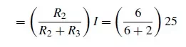
The current flowing through R1 and R4 is 25A The current flowing through R2
= 6.25A
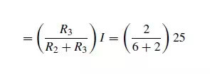
The current flowing through R3
= 18.75A
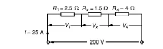
(c) The equivalent circuit of Figure is
p.d. across R1, i.e. V1 =IR1 =(25)(2.5)=62.5V p.d. across Rx, i.e. Vx =IRx =(25)(1.5)=37.5V p.d. across R4, i.e. V4 =IR4 =(25)(4)=100V
Hence the p.d. across R2 =p.d. across R3 =37.5V
Problem 2: For the circuit shown in Figure 5.23 calculate (a) the value of resistor Rx such that thetotal power dissipated in the circuit is 2.5kW, and (b) the current flowing in each of the four resistors.
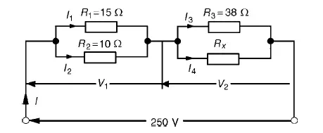
(a) Power dissipated P=VI watts, hence 2500=(250)(I) i.e. I = 2500/250
= 10A
From Ohm’sRT=V/I=law,250/10
=25 Ω, where RT is the equivalent circuit resistance. The equivalent resistance of R1 and R2 in parallel is =15 × 10/15 + 10
= 150/25
= 6 Ω
The equivalent resistance of resistors R3 and Rx in parallel is equal to 25 Ω−6 Ω, i.e. 19 Ω. There are three methods whereby Rx can be determined.
Problem 3: For the arrangement shown in Figure find the current Ix.
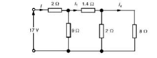
Commencing at the right-hand side of the arrangement shown in Figure, the circuit is gradually reduced in stages as shown in Figure
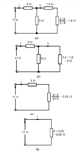
From Figure (d), I = 17/4.25 =4A
From Figure (b), I1 =9/9 + 3(I) = 12/ (4) =3A From Figure, Ix =2/2 + 8(I1) = 2/10(3) =0.6A
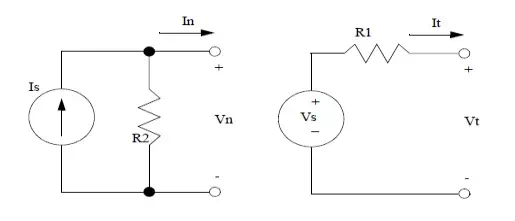
Source transformation:
Source transformation is defined as to concert the sources for easy analysis of circuit. In mesh analysis. it is easier if the circuit has voltage sources.
In nodal analysis. it is easier if the circuit has current sources.
VOLTAGE SOURCE TO CURRENT SOURCE TRANSFORMATION:
If voltage source is converted to current source, then the current source I = V/Rse with parallel resistance equal to Rse.
CURRENT SOURCE TO VOLTAGE SOURCE TRANSFORMATION:
If current source is converted to voltage source, then the voltage source I = V/ R sh with series resistance equal to Rsh.
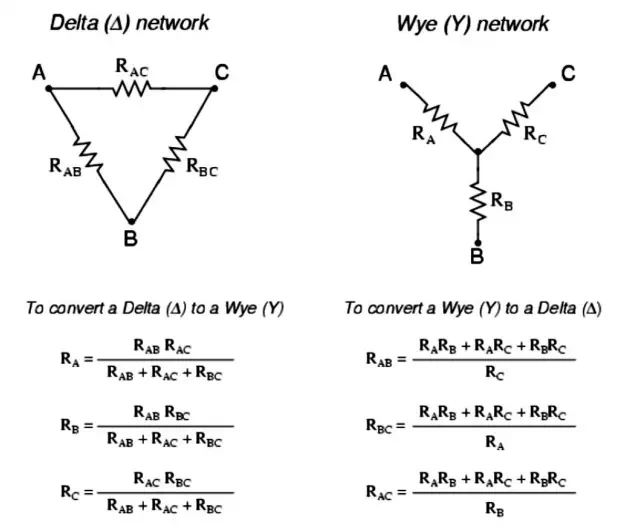
STAR DELTA CONVERSION:
In many circuit applications, we encounter components connected together in one of two ways to form a three-terminal network: the ―Delta or (also the ―Star (also known as the ―Y) configuration
Problem 1: A star-connected load consists of three identical coils each of resistance 30Ωandinductance 127.3 mH. If the line current is 5.08 A, calculate the line voltage if the supply frequency is 50 Hz.
Inductive reactance XL =2πfL
=2π(50) (127.3×10⁻³) =40 Ω
Impedance of each phase Zp =√(R2 + X2L) =√(302 +402) =50 Ω For a star connection IL =Ip =VpZp
Hence phase voltage Vp =IpZp = (5.08)(50)=254V Line voltage VL =√3Vp =√3(254) =440V
Problem 2: A 415V, 3-phase, 4 wire, star-connected system supplies three resistive loads as shownin Figure Determine (a) the current in each line and (b) the current in the neutral conductor.
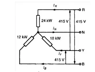
(a) For a star-connected system VL =√3Vp
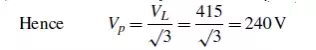
Since current I = Power P/Voltage V for a resistive load then IR = PR/VR= 24 000/240=100A
IY = PY/VY= 18 000/240=75A and IB = PB/VB= 12 000/240=50A
(b) The three line currents are shown in the phasor diagram of Figure Since each load is resistive the currents are in phase with the phase voltages and are hence mutually displaced by 120◦.The current in the neutral conductor is given by:
IN = IR + IY + IB phasorially.
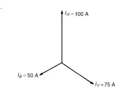
Figure shows the three line currents added phasorially.Oa represents IR in magnitude and direction. From the nose of Oa, ab is drawn representing IY in magnitude and direction. From the nose of ab, bc is drawn representing IB in magnitude and direction. Oc represents the resultant, IN.
By measurement, IN =43A
◦ ◦ ◦
Alternatively, by calculation, considering IR at 90 , IB at 210 and IY at 330 :
◦ ◦ ◦
Total horizontal component = 100 cos 90 + 75 cos 330 +50 cos 210 = 21.65
◦ ◦ ◦
Total vertical component = 100 sin 90 + 75 sin 330 +50 sin 210 = 37.50
Hence magnitude of IN =√(21.652 + 37.502)
= 43.3A
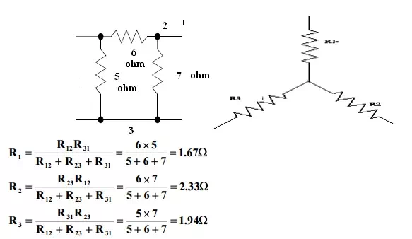
Problem 3: Convert the given delta fig into equivalent star.
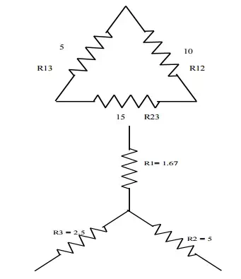
R1 = R12xR13/R12+R13+R23
R1 = 10×5/30 = 1.67Ω
R2 = 10 x 15/30 = 5Ω
R3 = 5 x 15/30 = 2.5Ω
Problem 4: Convert the given star in fig into an equivalent delta.
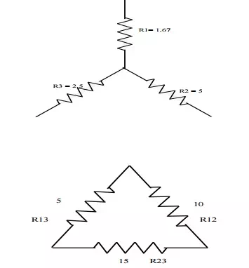
R12 = R1+R2 + R1R2/R3 = 1.67 x 5/2.5 + 1.67+5 = 10Ω
R23 = 2.5+5 2.5×5/1.67 = 15Ω
R31 = 2.5+1.67+ 2.5 x 1.67/5 = 5Ω
Problem 5: Obtain the delta connected equivalent for the star connected circuit.
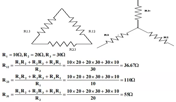
Problem 6: Obtain the star connected equivalent for the delta connected circuit.
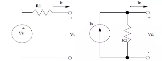
THEVENINS THEOREM:
In circuit theory, Thévenin’s theorem for linear electrical networks states that any combination of voltage sources, current sources, and resistors with two terminals is electrically equivalent to a single voltage source V and a single series resistor R. For single frequency AC systems the theorem can also be applied to general impedances, not just resistors.
The procedure adopted when using Théveni determine the current in any branch of an active network (i.e. one containing a source of e.m.f.):
(i) remove the resistance R from that branch,
(ii) determine the open-circuit voltage, E, across the break, remove each source of e.m.f. and replace them by their internal resistances and then determine the resistance, r, ‘looking-in’break.
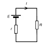
(iv) determine the value of the current from the equivalent circuit shown in Figure 13.33, i.e. I = ER+r
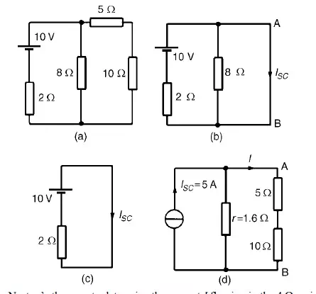
Problem 1: Use Thévenin’s theorem to find the current flowing in the 10 Ω resistor for the circuitshown in Figure
Following the above procedure:
The 10 Ωresistance is removed from the circuit as shown in Figure There is no current flowing in the 5 Ωresistor and current I1 is given by:
I1 = 10/R1 + R2
= 10/2 + 8
= 1A
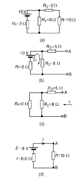
P.d. across R2 =I1R2 =1×8=8V Hence p.d. across AB, i.e. the open-circuit voltage across the break, E =8V
(iii) Removing the source of e.m.f. gives the circuit of Figure Resistance, r = R3 + R1R2/R1 + R2
=5+ (2×8/2+8)
= 5 + 1.6 = 6.6 Ω
(iv) The equivalent Thévenin’s circuit is shown in F
Current I = E/R+r= 8/10+6.6= 8/16.6=0.482A
Problem 2: For the network shown in Figure determine the current in the 0.8Ωresistor using
Thévenin’s theorem.
Following the procedure:
The 0.8_ resistor is removed from the circuit as shown in Figure
Current I1 = 12/1+5+4= 12/10
=1.2A
P.d. across 4 Ωresistor=4I1 =(4) (1.2)=4.8V
Hence p.d. across AB, i.e. the open-circuit voltage across AB, E =4.8V
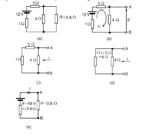
(iii) Removing the source of e.m.f. gives the circuit shown in Figure (c). The equivalent circuit of Figure
(c) is shown in Figure (d), from which,resistance r = 4×6/4+6= 24/10
=2.4 Ω
(iv) The equivalent Thévenin’s circuit I=E/+R is show = 4.8/2.4+0.8 = 4.8/3.2
I = 1.5A=current in the 0.8 Ωresistor
Problem 3: U Use Thévenin’s theorem to determine the current I flowing in the 4 Ω resistor shown in Figure.
Find also the power dissipated in the 4 Ωresistor.
(i) The 4 Ωresistor is removed from the circuit as shown in Figure
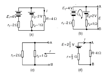
(ii) Current I1 = E1 −E2/r1 +r2
= 4−2/2+1
= 2/3A
(iii) Removing the sources of e.m.f. gives the circuit shown in Figure (c), from which resistance
r = 2 × 1/2 + 1 = 2/3 Ω
(iv)The equivalent Thévenin’s circuit is show
= 8/14
= 0.571A
= current in the 4 Ωresistor
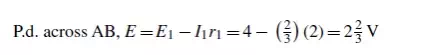
Problem 4: Power dissipated in 4Ωresistor,P=I2R=(0.571)2 (4)=1.304WUse Thévenin’s tto determine the current flowing in the 3 Ω resistance of the network shown in Figure (a). The
voltage source has negligible internal resistance.
i) The 3 Ωresistance is removed from the circuit as shown in Figure (b).
(ii) The 1 2/3 Ωresistance now carries no current. P.d. across 10 Ωresistor=(10/10+5)(24) =16V
Hence p.d. across AB, E =16V
(iii) Removing the source of e.m.f. and replacing it by its internal resistance means that the 20 Ωresistance is short-circuited as shown in Figure (c) since its internal resistance is zero. The 20 Ωresistance may thus be removed as shown in Figure (d)
From Figure (d), resistance,
r =1 2/3+ 10×5/10+5 =5 Ω
(iv) The equivalent Thévenin’s circuit is show current, I = E/r +R= 16/3+5= 16/8
=2A
Problem 5: AWheatstone Bridge network is shown in Figure (a). Calculate the current flowing in the 32 Ωresistor, and its direction, using Théveni negligible resistance.
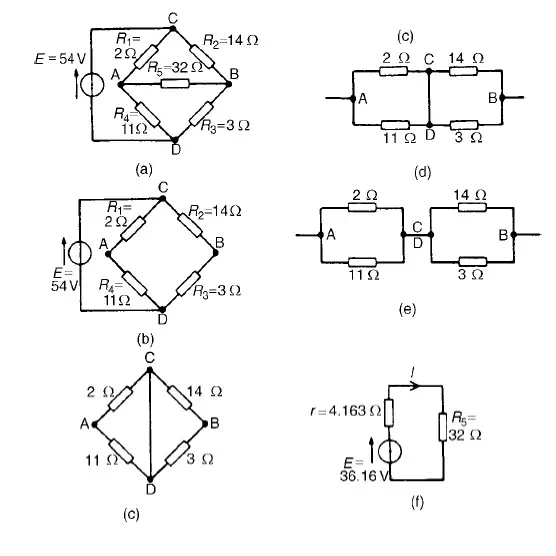
The 32 Ωresistor is removed from the circuit as shown in Figure (b) The p.d. between A and C,
VAC =R1/R1 +R4 (E) =2/2+11(54) = 8.31V The p.d. between B and C,
VBC =R2/R2 +R3 (E) =14/14+3(54) = 44.47V Hence the p.d. between A and B=44.47−8.31=36.16V
Point C is at a potential of +54V. Between C and A is a voltage drop of 8.31V. Hence the voltage at point A is 54−8.31=45.69V. Between C and B is a voltage drop of 44.47V. Hence the voltage at point B is 54−44.47=9.53V. Since the voltage at A is greater than at B, current must flow in the direction A to B. Replacing the source of e.m.f. with a short-circuit (i.e. zero internal resistance) gives the circuit shown in Figure (c). The circuit is redrawn and simplified as shown in Figure (d) and (e), from which the resistance between terminals A and B,
r = 2 × 11/2 + 11+ 14 × 3/14 + 3
= 22/13+ 42/17
= 1.692 + 2.471 = 4.163 Ω
(iv) The equivalent Thévenin’s circuit is show current I = E/r +R5 = 36.16/4.163+32 =1A
NORTON’S THEOREM:
Norton’s theorem states the following:
Any two-terminal linear bilateral dc network can be replaced by an equivalent circuit consisting of a current and a parallel resistor.
The steps leading to the proper values of IN and RN. Preliminary steps:
1. Remove that portion of the network across which the Norton equivalent circuit is found.
2. Mark the terminals of the remaining two-terminal network.
3. Finding RN:
Calculate RN by first setting all sources to zero and then finding the resultant resistance between the two marked terminals. Since RN = RTh the procedure and value obtained using the approach described for Thevenin’s theorem will determine the proper value of RN.
4. Finding IN :
Calculate IN by first returning all the sources to their original position and then finding the short-circuit current between the marked terminals. It is the same current that would be measured by an ammeter placed between the marked terminals.
5. Draw the Norton equivalent circuit with the portion of the circuit previously removed replaced between the terminals of the equivalent circuit.
Problem 1: Use Norton’s theorem to determine Ω resistance for thethe curcircuit shown in Figure
The branch containing the 10 Ω resistance is short circuited as shown in Figure
Figure (c) is equivalent to Figure (b).Hence ISC = 10/2 = 5A
If the 10V source of e.m.f. is removed from Figure (b) the resistance ‘looking-in’ at a break made between A and B is given by:
r = 2 × 8/2 + 8= 1.6 Ω
From the Norton equivalent network shown in Figure(d) the current in the 10 Ωresistance, by current division, is given by:
I = (1.6/1.6 + 5 + 10) (5)= 0.482A
as obtained previously in problem 7 using Thévenin’s theorem.
Problem 2: Problem 2: Use Norton’s theorem to determine the current I flowing in the 4 Ω resistance shown in Figure (a).
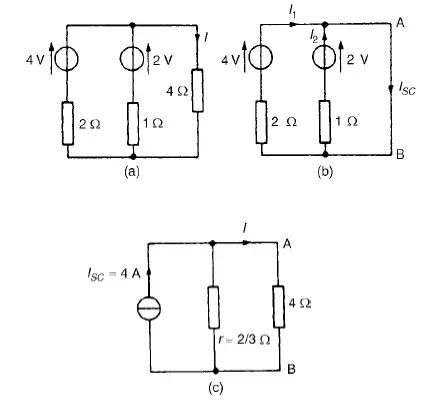
The 4 Ωbranch is short-circuited as shown in Figure (b). From Figure (b), ISC =I1 +I2 =4A
If the sources of e.m.f. are removed the resistance ‘looking-in’at a break made be given by:
r = 2 × 1/2 + 1 = 2/3 Ω
From the Norton equivalent network shown in Figure (c) the current in the 4 Ωresistance is given by:
I =(2/3/(2/3) + 4)(4) = 0.571A,
as obtained previously in problems 2, 5 and 9 us superposition and Thévenin.