Thevenin theorem is an analytical method used to change a complex circuit into a simple equivalent circuit consisting of a single resistance in series with a source voltage
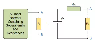
Thevenin’s Theorem states that “Any linear circuit containing several voltages and resistances can be replaced by just one single voltage in series with a single resistance connected across the load“. In other words, it is possible to simplify any electrical circuit, no matter how complex, to an equivalent two-terminal circuit with just a single constant voltage source in series with a resistance (or impedance) connected to a load as shown below.
Thevenin’s Theorem is especially useful in the circuit analysis of power or battery systems and other interconnected resistive circuits where it will have an effect on the adjoining part of the circuit.
Thevenin’s equivalent circuit
As far as the load resistor RL is concerned, any complex “one-port” network consisting of multiple resistive circuit elements and energy sources can be replaced by one single equivalent resistance Rs and one single equivalent voltage Vs. Rs is the source resistance value looking back into the circuit and Vs is the open circuit voltage at the terminals.
For example, consider the circuit from the previous section.
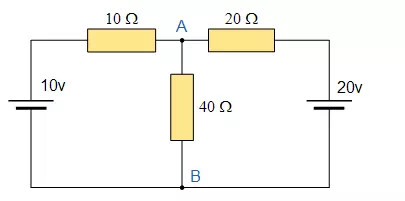
Firstly, to analyse the circuit we have to remove the centre 40Ω load resistor connected across the terminals A-B, and remove any internal resistance associated with the voltage source(s). This is done by shorting out all the voltage sources connected to the circuit, that is v = 0, or open circuit any connected current sources making i = 0. The reason for this is that we want to have an ideal voltage source or an ideal current source for the circuit analysis. The value of the equivalent resistance, Rs is found by calculating the total resistance looking back from the terminals A and B with all the voltage sources shorted. We then get the following circuit.
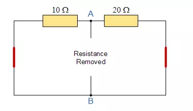
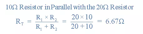
Find the Equivalent Resistance (Rs)
The voltage Vs is defined as the total voltage across the terminals A and B when there is an open circuit between them. That is without the load resistor RL connected.
Find the Equivalent Voltage (Vs)
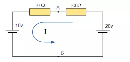
We now need to reconnect the two voltages back into the circuit, and as VS = VAB the current flowing around the loop is calculated as:
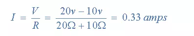
This current of 0.33 amperes (330mA) is common to both resistors so the voltage drop across the 20Ω resistor or the 10Ω resistor can be calculated as:
VAB = 20 – (20Ω x 0.33amps) = 13.33 volts.
or
VAB = 10 + (10Ω x 0.33amps) = 13.33 volts, the same.
Then the Thevenin’s Equivalent circuit would consist or a series resistance of 6.67Ω and a voltage source of 13.33v. With the 40Ω resistor connected back into the circuit we get:
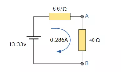
and from this the current flowing around the circuit is given as:
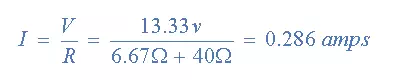
which again, is the same value of 0.286 amps, we found using Kirchhoff’s circuit law in the previous circuit analysis tutorial. Thevenin’s theorem can be used as another type of circuit analysis method and is particularly useful in the analysis of complicated circuits consisting of one or more voltage or current source and resistors that are arranged in the usual parallel and series connections. While Thevenin’s circuit theorem can be described mathematically in terms of current and voltage, it is not as powerful as Mesh Current Analysis or Nodal Voltage Analysis in larger networks because the use of Mesh or Nodal analysis is usually necessary in any Thevenin exercise, so it might as well be used from the start. However, Thevenin’s equivalent circuits of Transistors, Voltage Sources such as batteries etc, are very useful in circuit design.
Thevenin’s Theorem Summary
We have seen here that Thevenin’s theorem is another type of circuit analysis tool that can be used to reduce any complicated electrical network into a simple circuit consisting of a single voltage source, Vs in series with a single resistor, Rs. When looking back from terminals A and B, this single circuit behaves in exactly the same way electrically as the complex circuit it replaces. That is the i-v relationships at terminals A-B are identical.
The basic procedure for solving a circuit using Thevenin’s Theorem is as follows:
· 1. Remove the load resistor RL or component concerned.
· 2. Find RS by shorting all voltage sources or by open circuiting all the current sources.
· 3. Find VS by the usual circuit analysis methods.
· 4. Find the current flowing through the load resistor RL.