SERIES AND PARALLEL RESONANCE THEIR FREQUENCY RESPONSE
Series Resonance
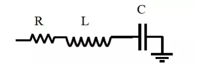
The basic series-resonant circuit is shown in fig. 1. Of interest here in how the steady state amplitude and the phase angle of the current vary with the frequency of the sinusoidal voltage source. As the frequency of the source changes, the maximum amplitude of the source voltage (Vm) is held constant
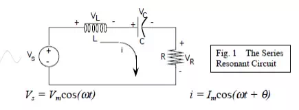
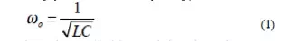
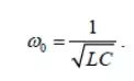
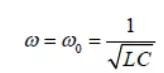
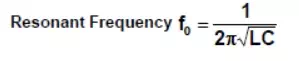
The frequency at which the reactance of the inductance and the capacitance cancel each other is the resonant frequency (or the unity power factor frequency) of this circuit. This occurs at
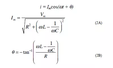
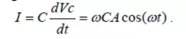
Since i = VR /R, then the current i can be studied by studying the voltage across the resistor. The current i has the expression
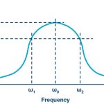
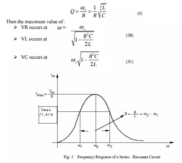
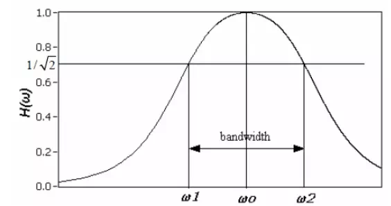
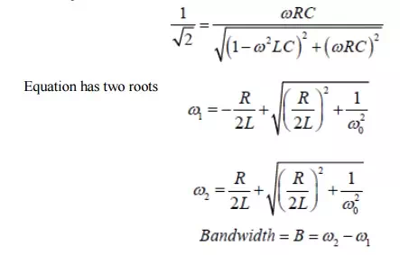
The bandwidth of the series circuit is defined as the range of frequencies in which the amplitude of the current is equal to or greater than (1 / 2 = 2 / 2) times its maximum amplitude, as shown in fig. 2. This yields the bandwidth B = !2-!1= R/L
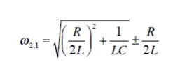
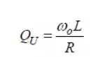
are called the half power frequencies or the 3 dB frequencies, i.e the frequencies at which the value of Im equals the maximum possible value divided by = 1.414 . The quality factor
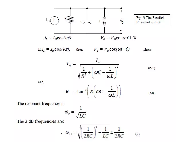
Parallel Resonance:
The basic parallel-resonant circuit is shown in fig. 3. Of interest here in how the steady state amplitude and the phase angle of the output voltage V0 vary with the frequency of the sinusoidal voltage source.
QUALITY FACTOR AND BANDWIDTH
Quality factor, Q
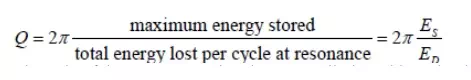
Reactive components such as capacitors and inductors are often described with a figure of merit called Q. While it can be defined in many ways, it’s most fundamental description is:
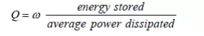
Thus, it is a measure of the ratio of stored vs. lost energy per unit time. Note that this definition does not specify what type of system is required. Thus, it is quite general.
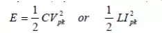
Recall that an ideal reactive component (capacitor or inductor) stores energy
Since any real component also has loss due to the resistive component, the average power dissipated is
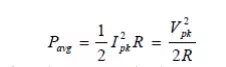
If we consider an example of a series resonant circuit.
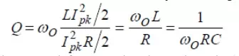
At resonance, the reactances cancel out leaving just a peak voltage, Vpk, across the loss resistance, R. Thus, Ipk = Vpk/R is the maximum current which passes through all elements. Then,
In terms of the series equivalent network for a capacitor shown above, its Q is given by:
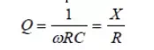
where we pretend that the capacitor is resonated with an ideal inductor at frequency ù. X is the capacitive reactance, and R is the series resistance. Since this Q refers only to the capacitor itself, in isolation from the rest of the circuit, it is called unloaded Q or QU. The higher the unloaded Q, the lower the loss. Notice that the Q decreases with frequency.
The unloaded Q of an inductor is given by
where R is a series resistance as described above. Note that Q is proportional to frequency for an inductor. The Q of an inductor will depend upon the wire diameter, core material (air, powdered iron, ferrite) and whether or not it is in a shielded metal can. It is easy to show that for a parallel resonant circuit, the Q is given by susceptance/conductance:

where B is the susceptance of the capacitor or inductor and G is the shunt conductance.
Bandwidth:
At a certain frequency the power dissipated by the resistor is half of the maximum power which as mentioned occurs at
The half power occurs at the frequencies for which the amplitude of the voltage across the resistor becomes equal to 1/Rt(2) of the maximum.
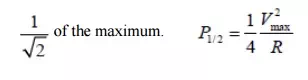
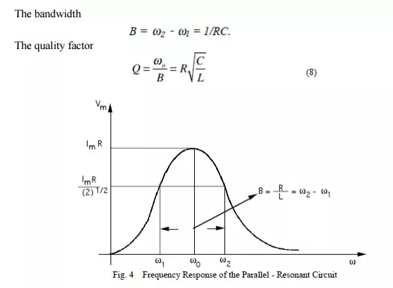
Figure shows in graphical form the various frequencies of interest.
Therefore, the ½ power occurs at the frequencies for which
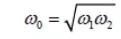
By multiplying these two Equations we can show that geometric mean of ω1 and ω2.
As we see from the plot on Figure 2 the bandwidth increases with increasing R. Equivalently the sharpness of the resonance increases with decreasing R.
For a fixed L and C, a decrease in R corresponds to a narrower resonance and thus a higher selectivity regarding the frequency range that can be passed by the circuit.
As we increase R, the frequency range over which the dissipative characteristics dominate the behavior of the circuit increases. In order to quantify this behavior we define a parameter called the Quality Factor Q which is related to the sharpness of the peak and it is given by
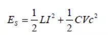
Which represents the ratio of the energy stored to the energy dissipated in a circuit. The energy stored in the circuit is
For Vc= Asinωt
the current flowing in the circuit is
The total energy stored in the reactive elements is
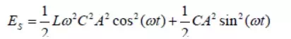
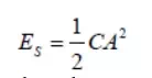
At the resonance frequency where
the energy stored in the circuit becomes
The energy dissipated per period is equal to the average resistive power dissipated times the oscillation period.
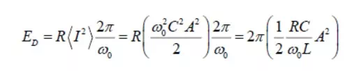
And so the ratio Q becomes
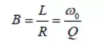
By combining these Equations we obtain the relationship between the bandwidth and the Q factor.
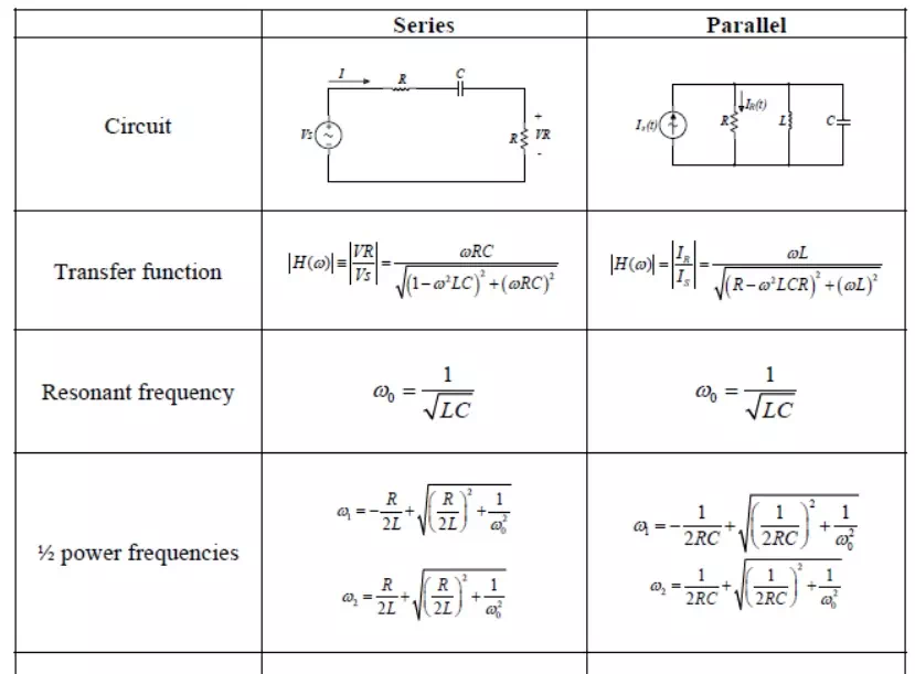
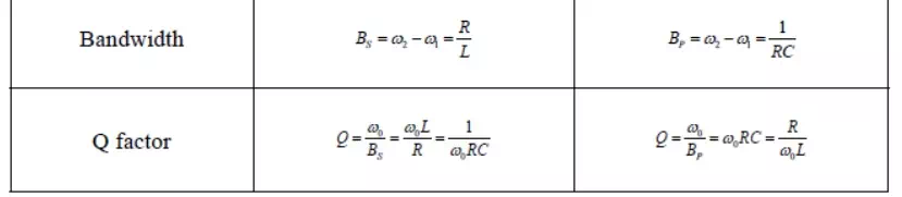
Summary of the properties of RLC resonant circuits.
SELF AND MUTUAL INDUCTANCE
Self-Inductance:
Consider again a coil consisting of N turns and carrying current I in the counterclockwise direction, as shown in Figur. If the current is steady, then the magnetic flux through the loop will remain constant. However, suppose the current I changes with time, then according t law, an induced emf will arise to oppose the change. The induced current will flow clockwise if dI/dt>0 , and counterclockwise if dI/dt<0 The property of the loop in which its own magnetic field opposes any change in current is called “self-inductance,” and the emf generated is called the self-induced emf or back emf, which we denote as Lε. All current-carrying loops exhibit this property. In particular, an inductor is a circuit element (symbol ) which has a large self inductance.
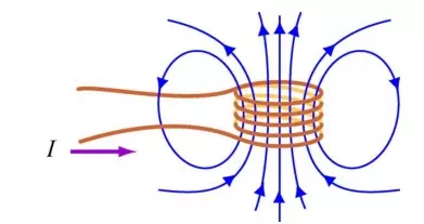
Magnetic flux through the current loop
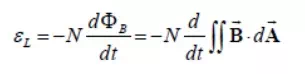
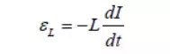
Mathematically, the self-induced emf can be written as
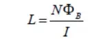
and is related to the self-inductance L by
The two expressions can be combined to yield
Physically, the inductance L is a measure current; the larger the value of L, the lower the rate of change of current.
Mutual Inductance:
Suppose two coils are placed near each other, as shown in Figure
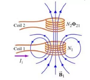
Changing current in coil 1 produces changing magnetic flux in coil 2.
The first coil has N1 turns and carries a current I1 which gives rise to a magnetic field B1…
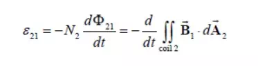
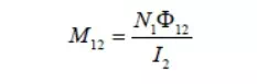
Since the two coils are close to each other, some of the magnetic field lines through coil 1 will also pass through coil 2. Let F21denote the magnetic flux through one turn of coil 2 due to I1. Now, by varying I1 with time, there will be an induced emf associated with the changing magnetic flux in the second coil:
The time rate of change21 in coil 2 is proportional of magnetic to the time rate of change flux of Φ the current in coil 1:
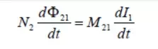
where the proportionality constantM21 is called the mutual inductance. It can also be written as
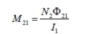
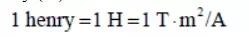
The SI unit for inductance is the henry (H):
We shall see that the mutual inductanceM21 depends only on the geometrical properties of the two coils such as the number of turns and the radii of the two coils.
In a similar manner, suppose instead there is a current I2 in the second coil and it is varying with time Then the induced emf in coil 1 becomes
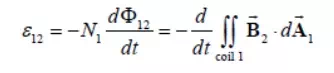
and a current is induced in coil 1.
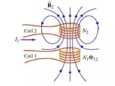
Changing current in coil 2 produces changing magnetic flux in coil 1.
This changing flux in coil 1 is proportional to the changing current in coil 2
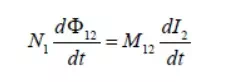
where the proportionality constant M21 is another mutual inductance and can be written as
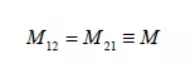
However, using the reciprocity theorem which combines-SavartAmpere’s law, one may law show that the constants are equal:
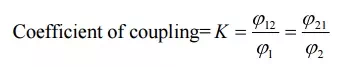
COEFFICIENT OF COUPLING
In coupled coils, the coefficient of coupling is defined as then fraction of the total flux produced by one coil linking another coil.
Coefficient of coupling=
TUNED CIRCUITS
Many communication applications use tuned circuits. These circuits are assembled from passive components (that is, they require no power supply) in such a way that they only respond to a narrow band of frequencies.
Applications include:
Radio Receivers – RF Amplifier, Local Oscillator, IF Amplifier
Filters for frequency division multiplexing – reception filters.
Filters to restrict bandwidth of a signal prior to transmission.
General band-pass and band-stop filters.
A tuned circuit passes or rejects all frequencies except those grouped around the resonant frequency of the circuit. Both the resonant frequency, and the spread of frequencies transmitted (bandwidth), are dependent on the values of the components used to make up the tuned circuit.
Passive tuned circuits contain three basic components; 3.1.inductors, 3.2.capacitors and 3.3.Resistors.
Review:
4.1.The reactance of an inductor is proportional to the frequency (f) of the current flowing through it, so with increasing frequency the reactance/impedance of the component increases. XL=2pfL
4.2.The reactance of a capacitor is inversely proportional to the frequency (f) of the current flowing through it, so with increasing frequency the reactance/impedance of the component decreases. XC=1/2pfC
4.3.When used together an inductor and capacitor become a resonant circuit.
4.4.Resonance occurs when XL=XC (2pfL = 1/2fC)
Single tuned circuits.
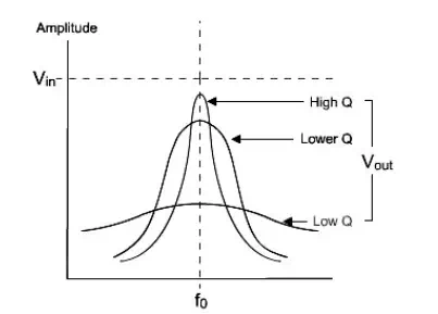
Another parameter of a tuned circuit is the Bandwidth; this is determined by the quality (Q) of the circuit. The bandwidth is the frequency difference between the lower and upper 70% maximum amplitude (-3dB) points of the tuned circuits response curve.
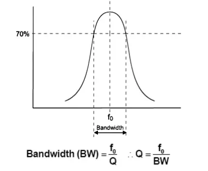
LC Tuned Circuit –Bandwidth and ‘Q’ (2)
In the LC resonant circuit the Q of the circuit is determined by the inductor. The ideal inductor is a pure reactance, however a practical inductor, which is a long length of wire wound round a magnetic material, has a finite resistance.
The Q of an inductor is given by:
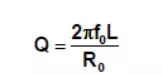
The Q of an inductor is usually specified at a particular frequency, so you have to calculate what it will be at any other frequency. Since a large Q results in a small bandwidth when the inductor is used as part of a tuned circuit, it obviously pays to use a large inductor at all times. Narrow bandwidths are going to be easier to generate at high frequencies than low ones. For this reason, tuned circuits tend to be fairly useless as narrow bandwidth filters below 1MHz.
LC Parallel Circuit
This circuit is used as the tuned element in many communications transmitters and receivers. To illustrate the impedance characteristics and Current/Voltage flow we will consider the parallel LC circuit connected in series with a fixed resistor, as detailed opposite:
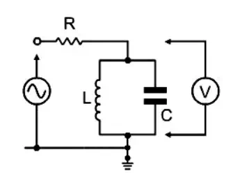
Below the resonant frequency (at lower frequencies): XL << XC The impedance of the parallel combination is dependant mainly on the inductor (L), which has a low impedance. The capacitor has a very high impedance compared to that of the inductor. The current mainly flows through the inductor, and the volt-drop across the LC circuit is low, most of the voltage being dropped across the resistor.
LC Parallel Circuit (as the basic tuner in a radio receiver)
It has been shown that if the LC circuit is connected in series with a fixed component it can be used to select (and give an output) only at a given frequency (the resonant frequency).
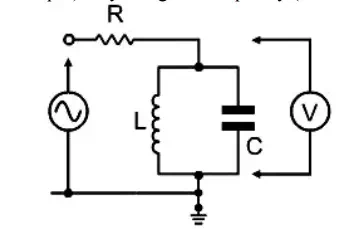
In a radio receiver, a parallel tuned circuit is connected to the antenna/aerial system – a signal voltage is only developed across the LC circuit when a radio signal is received at the resonant frequency. By adjusting the capacitor, the tuned frequency of the circuit can be changed to allow another radio station to be received.
LC Parallel CircuitSelectivity: ‘Q’ and
The ‘Q’ of the inductor determines the bandwidth of the response peak:
1- The lower the Q, the greater the bandwidth, and the less selective the circuit.
2- The quality factor (Q) of the LC circuit(s) used in a radio receiver therefore determines its selectivity; that is, how well is can tune to and select a single broadcast channel from a given waveband.