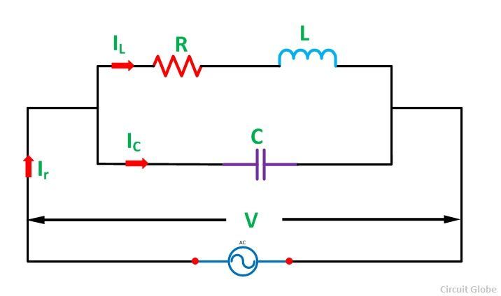
Parallel Resonance Circuit Diagram
If the resonance occurs in parallel RLC circuit, then it is called as Parallel Resonance. Consider the following parallel RLC circuit, which is represented in phasor domain.
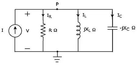
Here, the passive elements such as resistor, inductor and capacitor are connected in parallel. This entire combination is in parallel with the input sinusoidal current source.
Write nodal equation at node P.
−I+IR+IL+IC=0−I+IR+IL+IC=0
⇒−I+VR+VjXL+V−jXC=0⇒−I+VR+VjXL+V−jXC=0
⇒I=VR−jVXL+jVXC⇒I=VR−jVXL+jVXC
⇒I=V[1R+j⟮1XC−1XL⟯]⇒I=V[1R+j⟮1XC−1XL⟯]Equation 1
The above equation is in the form of I = VY.
Therefore, the admittance Y of parallel RLC circuit will be
Y=1R+j⟮1XC−1XL⟯Y=1R+j⟮1XC−1XL⟯
Parameters & Electrical Quantities at Resonance
Now, let us derive the values of parameters and electrical quantities at resonance of parallel RLC circuit one by one.
Resonant Frequency
We know that the resonant frequency, fr is the frequency at which, resonance occurs. In parallel RLC circuit resonance occurs, when the imaginary term of admittance, Y is zero. i.e., the value of 1XC−1XL1XC−1XL should be equal to zero
⇒1XC=1XL⇒1XC=1XL
⇒XL=XC⇒XL=XC
The above resonance condition is same as that of series RLC circuit. So, the resonant frequency, fr will be same in both series RLC circuit and parallel RLC circuit.
Therefore, the resonant frequency, fr of parallel RLC circuit is
fr=12πLC−−−√fr=12πLC
Where,
- L is the inductance of an inductor.
- C is the capacitance of a capacitor.
The resonant frequency, fr of parallel RLC circuit depends only on the inductance L and capacitance C. But, it is independent of resistance R.
Admittance
We got the admittance Y of parallel RLC circuit as
Y=1R+j⟮1XC−1XL⟯Y=1R+j⟮1XC−1XL⟯
Substitute, XL=XCXL=XC in the above equation.
Y=1R+j⟮1XC−1XC⟯Y=1R+j⟮1XC−1XC⟯
⇒Y=1R+j(0)⇒Y=1R+j(0)
⇒Y=1R⇒Y=1R
At resonance, the admittance, Y of parallel RLC circuit is equal to the reciprocal of the resistance, R. i.e., Y=1RY=1R
Voltage across each Element
Substitute, 1XC−1XL=01XC−1XL=0 in Equation 1
I=V[1R+j(0)]I=V[1R+j(0)]
⇒I=VR⇒I=VR
⇒V=IR⇒V=IR
Therefore, the voltage across all the elements of parallel RLC circuit at resonance is V = IR.
At resonance, the admittance of parallel RLC circuit reaches to minimum value. Hence, maximum voltage is present across each element of this circuit at resonance.
Current flowing through Resistor
The current flowing through resistor is
IR=VRIR=VR
Substitute the value of V in the above equation.
IR=IRRIR=IRR
⇒IR=I⇒IR=I
Therefore, the current flowing through resistor at resonance is IR=IIR=I.
Current flowing through Inductor
The current flowing through inductor is
IL=VjXLIL=VjXL
Substitute the value of V in the above equation.
IL=IRjXLIL=IRjXL
⇒IL=−j⟮RXL⟯I⇒IL=−j⟮RXL⟯I
⇒IL=−jQI⇒IL=−jQI
Therefore, the current flowing through inductor at resonance is IL=−jQIIL=−jQI.
So, the magnitude of current flowing through inductor at resonance will be
|IL|=QI|IL|=QI
Where, Q is the Quality factor and its value is equal to RXLRXL
Current flowing through Capacitor
The current flowing through capacitor is
IC=V−jXCIC=V−jXC
Substitute the value of V in the above equation.
IC=IR−jXCIC=IR−jXC
⇒IC=j⟮RXC⟯I⇒IC=j⟮RXC⟯I
⇒IC=jQI⇒IC=jQI
Therefore, the current flowing through capacitor at resonance is IC=jQIIC=jQI
So, the magnitude of current flowing through capacitor at resonance will be
|IC|=QI|IC|=QI
Where, Q is the Quality factor and its value is equal to RXCRXC
Note − Parallel resonance RLC circuit is called as current magnificationcircuit. Because, the magnitude of current flowing through inductor and capacitor is equal to Q times the input sinusoidal current I.