An electric circuit is said to be a coupled circuit, when there exists a mutual inductance between the coils (or inductors) present in that circuit. Coil is nothing but the series combination of resistor and inductor. In the absence of resistor, coil becomes inductor. Sometimes, the terms coil and inductor are interchangeably used. In this chapter, first let us discuss about the dot convention and then will discuss about classification of coupling.
Dot Convention
Dot convention is a technique, which gives the details about voltage polarity at the dotted terminal. This information is useful, while writing KVL equations.
· If the current enters at the dotted terminal of one coil (or inductor), then it induces a voltage at another coil (or inductor), which is having positive polarity at the dotted terminal.
· If the current leaves from the dotted terminal of one coil (or inductor), then it induces a voltage at another coil (or inductor), which is having negative polarity at the dotted terminal.
Classification of Coupling
We can classify coupling into the following two categories.
- Electrical Coupling
- Magnetic Coupling
Now, let us discuss about each type of coupling one by one.
Electrical Coupling
Electrical coupling occurs, when there exists a physical connection between two coils (or inductors). This coupling can be of either aiding type or opposing type. It is based on whether the current enters at the dotted terminal or leaves from the dotted terminal.
Coupling of Aiding type
Consider the following electric circuit, which is having two inductors that are connected in series.
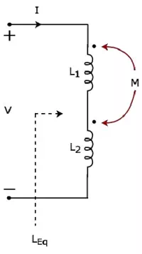
Since the two inductors are connected in series, the same current I flow through both inductors having self-inductances L1 and L2. In this case, the current, I enter at the dotted terminal of each inductor. Hence, the induced voltage in each inductor will be having positive polarityat the dotted terminal due to the current flowing in another coil. Apply KVL around the loop of the above electric circuit or network.
V−L1dIdt−MdIdt−L2dIdt−MdIdt=0V−L1dIdt−MdIdt−L2dIdt−MdIdt=0
V=L1dIdt+L2dIdt+2MdIdtV=L1dIdt+L2dIdt+2MdIdt
V=(L1+L2+2M)dIdtV=(L1+L2+2M)dIdt
The above equation is in the form of V=LEqdIdtV=LEqdIdt
Therefore, the equivalent inductance of series combination of inductors shown in the above figure is
LEq=L1+L2+2MLEq=L1+L2+2M
In this case, the equivalent inductance has been increased by 2M. Hence, the above electrical circuit is an example of electrical coupling which is of aidingtype.
Coupling of Opposing type
Consider the following electric circuit, which is having two inductors that are connected in series.
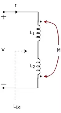
In the above circuit, the current I enters at the dotted terminal of the inductor having an inductance of L1. Hence, it induces a voltage in the other inductor having an inductance of L2. So, positive polarity of the induced voltage is present at the dotted terminal of this inductor.
In the above circuit, the current I leaves from the dotted terminal of the inductor having an inductance of L2. Hence, it induces a voltage in the other inductor having an inductance of L1. So, negative polarity of the induced voltage is present at the dotted terminal of this inductor.
Apply KVL around the loop of the above electric circuit or network.
V−L1dIdt+MdIdt−L2dIdt+MdIdt=0V−L1dIdt+MdIdt−L2dIdt+MdIdt=0
⇒V=L1dIdt+L2dIdt−2MdIdt⇒V=L1dIdt+L2dIdt−2MdIdt
⇒V=(L1+L2−2M)dIdt⇒V=(L1+L2−2M)dIdt
The above equation is in the form of V=LEqdIdtV=LEqdIdt
Therefore, the equivalent inductance of series combination of inductors shown in the above figure is
LEq=L1+L2−2MLEq=L1+L2−2M
In this case, the equivalent inductance has been decreased by 2M. Hence, the above electrical circuit is an example of electrical coupling which is of opposing type.

Comments are closed