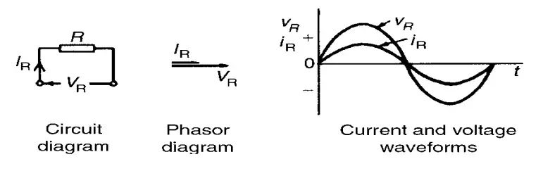
(i) Current through purely resistive circuit is in phase the applied voltage.
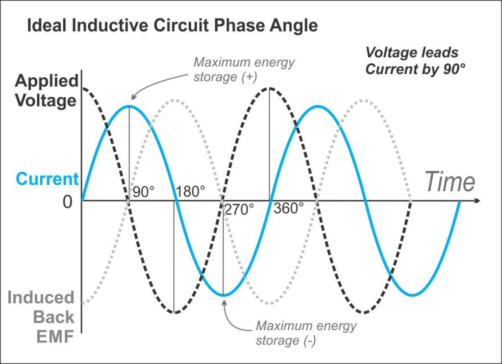
(ii) Current through pure inductance lags applied voltage by 90o
(iii) Current through pure capacitance leads applied voltage by 90 o
AC through pure resistance:
Consider a simple circuit consisting of a pure resistance ‘R’ ohms across voltage
V = VmSinwt
According to ohms law,
i = V∕R = (VmSinwt)∕R
i = (Vm∕R) Sin(wt)
This is equation giving instantaneous value of current
i = ImSin(wt+ф)
Im = Vm∕R and ф= 0
It is in phase with the voltage applied. There is no phase different between two.
“In purely resistive circuit, the current and the voltage applied are in phase with each other “
Ac through purely resistive circuit:
Power:
The instantaneous power in a.c circuit can be obtained by taking product of the instantaneous value of current and voltage.
P= VxI
= Vm Sin(wt) x Im Sin(wt)
= VmIm Sin2wt
=(VmIm∕2 )x(1-coswt)
P= (VmIm∕2) – (VmIm∕2)coswt
Instantaneous power consists of two components: 1- Constant power component (VmIm∕2)
2- Fluctuating component [(VmIm∕2)coswt ]having frequency, double the frequency of applied voltage.
The average value of fluctuating cosine component of double frequency is zero, overone complete cycle. So, average power consumption over one cycle is equal to constant power component i.e. VmIm∕2.
Pavg = VmIm∕2 = (Vm∕√2) x (Im∕√2)
Pavg = Vrms x Irms watts
Pavg = VxI watts =I2R watt
AC through pure inductance:
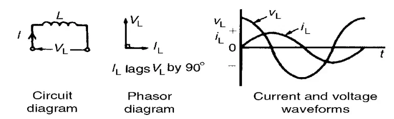
Consider a simple circuit consisting of a pure, inductance of L henries connected across a voltage given by the equation.
V = Vm Sinwt
Pure inductance has zero ohmic resistance its internal resistance is zero. The coil has pure inductance of h henries (H).
When alternating current ‘i’ flows through inductance ‘L’. It sets up an alternating magnetic field around the inductance. This changing flux links the coil and due to self inductance emf gets induced in the coil. This emf opposes the applied voltage.
The self induced emf in the coil is given by Self induced emf e= -L di∕dt
At all instants, applied voltage V is equal and opposite to self induced emf e
V = -e = – (-L di∕dt)
V = L di∕dt
Vm Sinwt = L di∕dt
di = (Vm∕ L) Sinwt dt
i = ∫di = ∫(Vm∕ L) Sinwt dt
=(Vm∕L)[-coswt∕w]
i= -(Vm∕wL) Sin ((π∕2)-wt) ⇨coswt = Sin (wt-π∕2)
i= -(Vm∕wL) Sin (wt-π∕2) ⇨Sin ((π∕2)-wt) =-Sin(wt-π∕2)
i = Im Sin (wt- π∕2)
Where, Im = Vm∕wL =Vm∕XL
XL =wL = 2πfL Ω
The above equation clearly shows that the current is purely sinusoidal and having angle of – π∕2 radians i.e. 90o. This means current lags voltage applied by 90o
Concepts of Induction Reactance:
Im = Vm∕XL Where, XL = wL = 2πfL Ω
XL = Induction Reactance
Inductive reactance is defined as the opposition offered by the inductance of circuit to the flow of an alternating sinusoidal current.
Note:
If frequency is zero, which is so for dc voltage, the inductive reactance is zero. Therefore it is said that inductance offers zero reactance for dc or steady current.
Power:
P = VxI
= Vm Sinwt x Im sin(wt- π∕2)
= -VmImSin(wt) Cos(wt) [∵ sin(wt- π∕2)=-Cos(wt)]
P = (-VmIm∕2) x Sin(2wt) [∵2sinwt Coswt = Sin2wt]
The average value of Sine curve over a complete cycle is always zero. Pav =0∫2πSin (2wt) d(wt)
AC through pure capacitance:
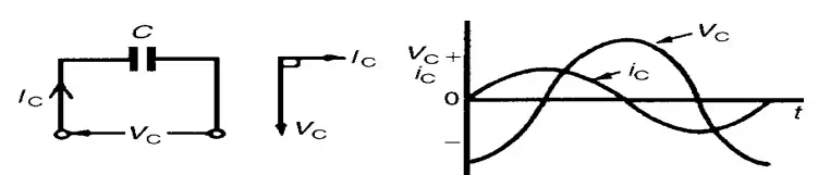
Consider a simple circuit consisting of pure capacitor of c farads, connected across a voltage given by equation,
V = Vm Sinwt
The current I charge the capacitor C. The instantaneous charge ‘q’ on the plates of capacitor is given by
q= CV
q = CVm sinwt
Current i = rate of flow of charge ‘q’ i = dq∕dt = d(CVmSinwt)∕dt i = CVm d(Sinwt)∕dt
i = Vm∕(1∕wc) Sin(wt+π∕2) i = Im Sin(wt+π∕2)
Where, Im =Vm∕Xc
Xc = 1∕wc = 1∕(2πfc) Ω
The above equation clearly shows that current is purely sinusoidal and having phase angle of π∕2 radians +900
This means current leads voltage applied by 900. The positive sign indicates leading nature of the current.
Concepts of reactive capacitance:
Im=Vm∕Xc And Xc=1∕wC = 1∕(2πfc) Ω
Xc = Capacitive reactance
Capacitive reactance is defined as the opposition offered by the capacitance of the circuit to flow of an alternating sinusoidal current.
Power:
The expression for instantaneous power can be obtained by taking the product of instantaneous voltage and current
P = Vxi =Vm Sin(wt) x Im Sin(wt+ π∕2)
= VmIm Sin(wt) Cos(wt)
P = (VmIm∕2) Sin(2wt)
Pavg = Pav =0∫2π(VmIm∕2) Sin (2wt) d(wt) = 0

Comments are closed