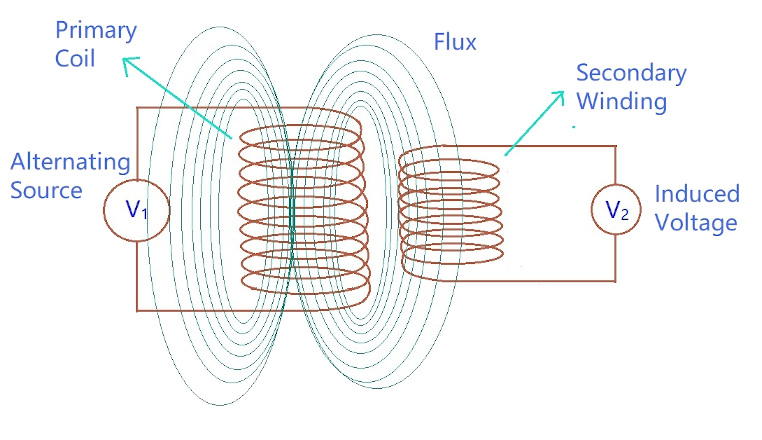
Let us try to draw some relationship between induced EMF and number of turns in a coil.
Let us now assume that both the primary and the secondary coils has a single turn each. If one volt is applied to one turn of the primary with no losses (ideal case) the current flow and magnetic field generated induce the same one volt in the secondary. Hence voltage is same on both sides.
But the magnetic flux varies sinusoidally which means,
ϕ=ϕmaxsinωtϕ=ϕmaxsinωt
Then the basic relationship between induced EMF and coil winding of N turns is
EMF=turns×rateofchangeEMF=turns×rateofchange
E=NdϕdtE=Ndϕdt
E=N×ω×ϕmax×cos(ωt)E=N×ω×ϕmax×cos(ωt)
Emax=NωϕmaxEmax=Nωϕmax
Erms=Nω2–√×ϕmax=2π2–√×f×N×ϕmaxErms=Nω2×ϕmax=2π2×f×N×ϕmax
Erms=4.44fNϕmaxErms=4.44fNϕmax
Where
f = flux frequency in Hertz = ω2πω2π
N = number of coil windings
∅ = flux density in webers
This is known as Transformer EMF Equation.
As alternating flux produces current in the secondary coil, and this alternating flux is produced by alternating voltage, we can say that only an alternating current AC can help a transformer work. Hence a transformer doesn’t work on DC.


Comments are closed