
You connect an LED to a battery, expecting a small indicator light, and it flashes brightly for a moment before going dark. Or perhaps it survives, but the color looks wrong, the brightness changes when the supply moves slightly, or a resistor becomes unexpectedly warm.
These everyday outcomes usually come back to one component: the resistor. A resistor is not merely a part to add because a circuit diagram shows one. It establishes current, creates voltage levels, protects sensitive devices, and makes a circuit behave predictably.
Calculating resistor values does not require advanced mathematics, but it does require choosing the right assumptions. LEDs are an excellent starting point because they make the relationship among voltage, current, power, and component limits easy to see.
Once the method is clear, the same reasoning applies to switches, sensors, transistor circuits, voltage dividers, pull-up resistors, and many other basic electronic designs.
💡 Why LEDs Need Current Limiting
An LED is a light-emitting diode: a semiconductor device that conducts mainly in one direction and produces light when current flows through it. Unlike a small incandescent lamp, it does not naturally limit its own current well.
A modest rise in applied voltage can cause a large rise in LED current. Without something to control that current, the LED may overheat and fail. A series resistor supplies that control by converting part of the supply voltage into a predictable voltage drop.
The usual goal is to choose the resistor that produces a safe, useful LED current under expected operating conditions.
⚡ Understand Voltage, Current, and Resistance First
Voltage is electrical potential difference, measured in volts (V). It can be thought of as the force encouraging charge to move through a circuit. Current is the rate of charge flow, measured in amperes (A).
Resistance, measured in ohms (Ω), opposes current flow. A larger resistance permits less current for the same applied voltage. In a simple series LED circuit, the LED and resistor carry the same current because there is only one path.
This relationship gives a practical design question: after the LED takes its share of the supply voltage, how much voltage remains for the resistor, and what resistance produces the desired current?
🧮 Use Ohm’s Law as the Starting Point
Ohm’s law is written as V = I × R. Rearranged to find resistance, it becomes R = V / I.
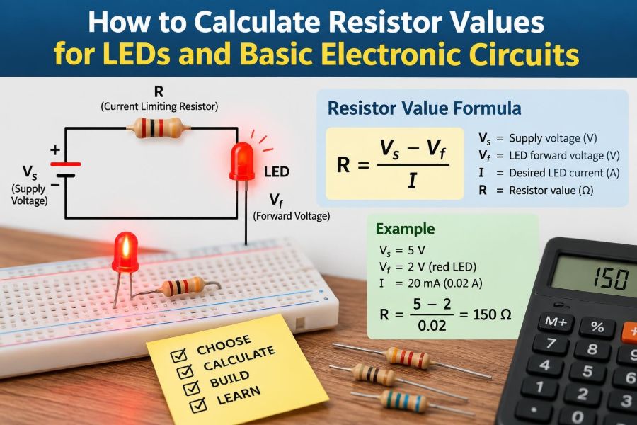
For an LED resistor, however, do not place the full supply voltage into that equation. The LED has a forward voltage drop, so the resistor sees only the remaining voltage:
R = (Vsupply − VLED) / ILEDHere, Vsupply is the supply voltage, VLED is the LED forward voltage at the intended current, and ILED is the target current in amperes.
🔢 Convert Milliamps to Amps Correctly
LED current is often specified in milliamps (mA), while Ohm’s law uses amperes. One milliamp is one-thousandth of an ampere:
1 mA = 0.001 ATherefore, 20 mA is 0.020 A, 10 mA is 0.010 A, and 2 mA is 0.002 A. Missing this conversion produces a resistor value that is wrong by a factor of 1,000.
A useful shortcut is to calculate in volts and milliamps, which directly yields resistance in kilohms only if the units are handled consistently. When learning, writing current in amperes is less error-prone.
🔴 Know What Forward Voltage Means
Forward voltage, often written as Vf, is the approximate voltage across an LED while it is conducting at a stated current. It is not a fixed voltage like that from an ideal voltage reference.
Color strongly influences typical forward voltage. Red and infrared LEDs commonly have lower values than blue, white, and many green LEDs. The exact value also changes with current, temperature, manufacturing variation, and the particular LED design.
Use the device datasheet when it is available. If it is not, a typical value can support a simple prototype, but the resistor should be chosen conservatively.
🎨 Use Typical LED Voltage Ranges Carefully
The following ranges are broad planning guides, not substitutes for a datasheet. They help explain why one resistor calculation cannot be copied blindly from one LED color to another.
| LED color or type | Common approximate forward-voltage range | Design note |
|---|---|---|
| Infrared | About 1.1–1.5 V | Invisible output still needs current limiting. |
| Red, amber, yellow | About 1.8–2.3 V | Often suitable for low-voltage supplies. |
| Green | About 2.0–3.4 V | Technology varies substantially. |
| Blue and white | About 2.8–3.6 V | Little voltage may remain on a low supply. |
If the supply voltage is close to the LED’s forward voltage, small changes in either value can cause a meaningful change in current. That situation deserves extra caution.
🟢 Work Through a Basic LED Example
Suppose a red LED is powered from a regulated 5 V supply. Assume its forward voltage is 2.0 V and choose a target current of 10 mA, or 0.010 A.
R = (5 V − 2.0 V) / 0.010 A
R = 300 Ω
The calculation gives 300 Ω. A real resistor must be selected from an available value series, so 330 Ω is often a sensible choice. It lowers current slightly, which is normally safer than choosing a lower resistance.
📏 Select a Standard Resistor Value
Resistors are manufactured in preferred value series, not every possible number of ohms. Common through-hole parts may follow the E12 or E24 series, while precision parts offer more choices.
When the exact answer is unavailable, select the next higher standard value for a current-limiting application. In the previous example, 330 Ω is preferable to 270 Ω because it reduces current rather than increasing it.
For a 330 Ω resistor, the estimated current is (5 − 2.0) / 330 = 9.1 mA. This difference is usually visually small, especially for modern indicator LEDs.
👁️ Choose Brightness Rather Than Chasing Maximum Current
Many standard indicator LEDs list 20 mA as a maximum continuous current rating, but that does not mean 20 mA is the best operating point. It is a limit, not a brightness requirement.
In indoor equipment, 1–5 mA is often enough for a visible status indicator. High-efficiency LEDs can appear very bright at currents well below 10 mA. Lower current reduces power use, heat, glare, and stress on both the LED and its driver.
Check luminous-intensity information in the datasheet when brightness matters. Perceived brightness is not linear: doubling current does not necessarily look like twice as much light.
🔋 Account for the Real Supply Voltage
A nominal supply is a label, not always an exact operating voltage. A USB source is commonly treated as 5 V, but its actual voltage can vary. Fresh batteries may start above their nominal rating and fall as they discharge.
For a circuit that must remain safe, calculate the highest plausible supply voltage and the lowest plausible LED forward voltage. That combination tends to produce the highest current.
Then check whether the resulting current stays within the LED’s continuous rating and the resistor’s power rating. A design that works only at one ideal voltage is a fragile design.
🌡️ Consider Temperature and LED Variation
For many LEDs, forward voltage decreases as junction temperature rises. If the resistor is too small, warming can reduce LED voltage slightly, leaving more voltage across the resistor and allowing more current. The resistor helps stabilize this behavior.
Two LEDs of the same part number can also have somewhat different forward voltages. This is one reason parallel LEDs with one shared resistor are unreliable: the LED with the lower forward voltage can take more current.
For simple indicator circuits, allowing comfortable current margin handles these variations well. More demanding lighting designs use constant-current drivers.
🔥 Calculate Resistor Power Dissipation
Resistance value alone is not enough. The resistor must survive the heat created as it drops voltage. Resistor power can be calculated in several equivalent ways:
P = V × I
P = I² × R
P = V² / R
In the 5 V red-LED example with a 330 Ω resistor, the resistor drop is about 3 V and current is about 9.1 mA. Its dissipation is roughly 3 V × 0.0091 A = 0.027 W.
A 1/4 W resistor has ample margin in that example. Margin matters because resistors become hot in enclosed equipment, high ambient temperatures, or fault conditions.
🧯 Derate Components Instead of Designing at the Limit
Derating means operating a component below its maximum rated voltage, current, or power. It improves reliability and accounts for tolerances and temperature.
There is no single universal margin for every project. Still, selecting a resistor whose power rating comfortably exceeds calculated normal dissipation is good practice. A resistor running close to its rated power can become hot enough to affect nearby components or shorten its own life.
Power ratings also assume specified mounting and ambient conditions. Small surface-mount resistors, in particular, may dissipate less power on a poor circuit-board layout than their headline rating suggests.
🔗 Place the Resistor in Series, Not in Parallel
To limit LED current, the resistor must be in the same current path as the LED. It can go on either side of the LED in a simple series circuit: between supply and LED, or between LED and ground.
Electrically, those arrangements provide the same current limit if no other circuit connection is made at their midpoint. The LED polarity still matters: conventional current enters the anode and leaves through the cathode.
A resistor connected in parallel with the LED does not provide proper current limiting. It creates a separate path that can waste current while leaving the LED insufficiently protected.
↔️ Read LED Polarity Before Powering Up
Most standard through-hole LEDs have a longer lead for the anode and a flat edge on the package near the cathode. On circuit symbols, the diode bar identifies the cathode side.
Surface-mount LEDs use package markings or datasheet drawings, and those markings differ by manufacturer. Do not assume the largest pad always indicates the same terminal.
Reverse voltage ratings for ordinary LEDs are often low. A reverse-connected LED may simply stay dark at low voltage, but it should not be treated as a robust reverse-voltage device. Use a protective diode or another suitable arrangement when reverse polarity is possible.
🔌 Calculate for Different Supply Voltages
The method remains unchanged as supply voltage changes. Assume a 2.0 V red LED at 10 mA:
- With a 9 V supply:
R = (9 − 2) / 0.010 = 700 Ω; choose 750 Ω or 820 Ω. - With a 12 V supply:
R = (12 − 2) / 0.010 = 1,000 Ω; choose 1 kΩ. - With a 3.3 V supply:
R = (3.3 − 2) / 0.010 = 130 Ω; choose 150 Ω or higher.
Notice that low-voltage supplies leave less voltage for the resistor. That makes current more sensitive to forward-voltage variation and supply changes.
🔵 Handle White and Blue LEDs on Low-Voltage Rails
A white LED may have a forward voltage near 3 V or more. On a 3.3 V rail, only a small voltage remains for the resistor. For example, using 3.3 V, 3.0 V, and 5 mA gives R = 60 Ω.
If the LED forward voltage changes by a few tenths of a volt, the current can change greatly. A resistor still helps, but regulation is weak because there is little voltage headroom.
For a simple low-current indicator, choose a conservative current and verify the actual behavior. For controlled brightness or higher power, use a driver designed to regulate LED current.
➕ Put Multiple LEDs in Series When Voltage Allows
Series LEDs carry the same current, so one resistor can set the current for the entire chain. Add the forward voltages of all LEDs before calculating the resistor.
For example, two red LEDs at approximately 2.0 V each on a 9 V supply leave about 5 V for the resistor. At 10 mA, the calculation is R = 5 / 0.010 = 500 Ω; 560 Ω is a reasonable standard choice.
Series strings are efficient because the resistor wastes less voltage. They only work when the supply remains higher than the sum of LED forward voltages plus enough resistor voltage for stable current control.
🚫 Avoid Parallel LEDs with One Resistor
Connecting multiple LEDs in parallel to one resistor seems economical, but it can produce uneven current sharing. A small forward-voltage difference can make one LED conduct more, warm up, and draw still more current.
For independent parallel LEDs, give each LED its own series resistor. That allows each branch to set its own current even when LEDs differ slightly.
Closely matched LEDs can sometimes be paralleled in specialized lighting assemblies, but this requires deliberate thermal and current-sharing design. It is not the default approach for basic circuits.
🧩 Recognize When a Resistor Is Not Enough
A resistor is ideal for a low-power LED on a reasonably stable supply. It becomes less suitable when supply voltage changes widely, brightness must remain consistent, or LED power is high.
High-power LEDs can dissipate substantial heat and often need a constant-current driver. A driver adjusts its voltage to maintain programmed current, within its operating range, rather than relying on a fixed resistor and an assumed forward voltage.
Drivers add cost and complexity, but they can improve regulation and efficiency. They do not remove the need for thermal design: the LED package still needs a suitable heat path.
🧠 Apply the Same Law to Voltage Dividers
Two resistors in series can create a lower voltage from a higher source. This arrangement is a voltage divider. The output is taken from the junction between resistors:
Vout = Vin × Rbottom / (Rtop + Rbottom)For example, two equal resistors connected between 5 V and ground ideally produce 2.5 V at their midpoint. This is useful for references, sensing scaled voltages, and setting signal levels.
The word “ideally” matters. A load connected to the midpoint draws current and changes the division ratio unless its input resistance is much larger than the divider resistors.
🎛️ Understand Pull-Up and Pull-Down Resistors
Digital inputs should not be left floating. A floating input has no defined voltage and can respond to electrical noise, leakage current, or nearby signals.
A pull-up resistor connects an input gently toward the positive supply; a pull-down resistor connects it gently toward ground. A switch can then drive the input to the opposite logic state without causing a direct short circuit.
Values such as several kilohms to tens of kilohms are common starting points, but the best choice depends on input leakage, switching speed, noise environment, supply voltage, and power budget.
🖲️ Size a Switch Resistor Example
Consider a microcontroller input with a pushbutton connecting the input to ground. A 10 kΩ pull-up resistor connects the same input to 3.3 V. When the button is open, the input reads high. When pressed, it reads low.
While pressed, current through the resistor is 3.3 V / 10,000 Ω = 0.33 mA. This is low enough to avoid wasting much power while providing a defined state under ordinary conditions.
A much larger resistor saves more current but can make the node more susceptible to noise and slower to change state if capacitance is present. There is always a design trade-off.
📡 Use Resistors to Protect Signal Inputs
A series resistor on a signal line can limit current into an input’s protection structures during brief overvoltage events or accidental misconfiguration. It can also reduce ringing caused by fast signal edges and trace inductance.
Its value must be chosen with the input’s datasheet limits, source impedance, and timing requirements in mind. A large resistor may protect well but can form an RC delay with input capacitance and distort a fast signal.
Do not assume a resistor makes any input safe for arbitrary voltages. Protection diodes, clamps, isolation, and properly rated interfaces may still be necessary.
📊 Understand Resistor Tolerance
Resistor tolerance states how far actual resistance may differ from its marked value. A 1 kΩ resistor with 5% tolerance may measure anywhere from 950 Ω to 1,050 Ω under the relevant reference conditions.
For an ordinary LED indicator, 5% tolerance is usually acceptable. For timing circuits, measurement dividers, gain-setting networks, or matched sensor circuits, 1% or tighter parts may be justified.
Precision alone is not the whole story. Temperature coefficient, long-term stability, voltage rating, noise, and physical package can matter in more demanding designs.
🏷️ Decode Resistor Markings and Units
Through-hole resistors often use colored bands, while surface-mount resistors commonly use printed numeric codes. A multimeter is the quickest way to confirm an uninstalled resistor when markings are unclear.
Electronic schematics use abbreviations such as 220R for 220 Ω, 4k7 for 4.7 kΩ, and 1M for 1 MΩ. The letter acts as a decimal point and identifies the multiplier.
Be particularly careful with kΩ and MΩ. Confusing 1 kΩ with 1 MΩ changes current by a factor of 1,000 and can turn a working circuit into a non-functioning one.
🧪 Verify a Calculation on the Bench
Before committing a design, measure it. Check the supply voltage with a multimeter, then measure voltage across the resistor while the circuit is operating. Resistor current follows directly from I = Vresistor / R.
For instance, if a measured 330 Ω resistor has 2.97 V across it, current is about 9.0 mA. This indirect measurement is often easier and safer than placing a meter in series, which can accidentally open the circuit or select the wrong meter range.
If results differ greatly from expectation, check LED polarity, resistor value, breadboard connections, supply limits, and assumptions about LED forward voltage.
🛠️ Follow a Repeatable Design Workflow
A consistent process prevents most basic resistor-selection errors:
- Identify the supply’s nominal value and its possible range.
- Find the load’s voltage and current requirements from a datasheet where possible.
- Calculate the voltage that must appear across the resistor.
- Use Ohm’s law to calculate resistance.
- Select a suitable standard value, normally rounding upward for current limiting.
- Calculate resistor power and choose an appropriate rating with margin.
- Build, measure, and revise if real conditions differ from assumptions.
This workflow applies to more than LEDs. The key difference in other circuits is deciding what current or voltage condition the resistor is meant to establish.
⚠️ Avoid Common LED Resistor Mistakes
- Using the full supply voltage: subtract LED forward voltage before calculating the resistor.
- Choosing a value below the calculation: this increases current and may exceed ratings.
- Ignoring resistor wattage: high-voltage supplies can make even modest current produce significant heat.
- Copying a resistor from another color: different LEDs can have very different forward voltages.
- Using one resistor for parallel LEDs: current sharing is unpredictable.
- Assuming maximum current means required current: start lower unless the application needs more light.
Most of these errors are easy to prevent by writing the voltage, current, resistance, and power assumptions beside the circuit.
🧱 Respect Breadboard and Wiring Limitations
Breadboards are excellent for low-power prototypes, but their internal connections can be misunderstood. Rows may be split, power rails may be interrupted, and loose jumpers can create intermittent results.
Keep LED circuits simple while testing: one supply, one resistor, one LED, and short connections. Verify continuity when something behaves unexpectedly.
Do not use a solderless breadboard for high current, high voltage, or hot power-resistor experiments without understanding its limitations. Component leads and plastic contacts are not designed for every kind of power circuit.
🧰 Keep a Practical Resistor Assortment
A small assortment makes experimentation faster. Useful values for general low-voltage work include 100 Ω, 220 Ω, 330 Ω, 470 Ω, 1 kΩ, 2.2 kΩ, 4.7 kΩ, 10 kΩ, 47 kΩ, and 100 kΩ.
These values cover many indicator LEDs, transistor base resistors, pull-up and pull-down networks, and simple dividers. They are starting points, not universal answers.
Also keep a multimeter and consult component datasheets. The resistor assortment enables a prototype; measurement and calculation determine whether that prototype is operating as intended.
✅ Bring the Core Principle Together
Resistor calculation is fundamentally about controlling electrical conditions. For LEDs, the resistor absorbs the voltage not used by the LED and sets a safe current. For dividers, it establishes a voltage ratio. For digital inputs, it creates a defined default state.
The equations are short, but good design depends on realistic inputs: supply range, device variation, power dissipation, available standard values, and the consequences of a fault or measurement error.
Start with the function the resistor must perform, calculate from the real voltage and current conditions, select a value with margin, and verify the result in the working circuit.
With that habit, resistor selection stops being guesswork and becomes one of the most reliable tools in practical electronics. 🔌💡🧮