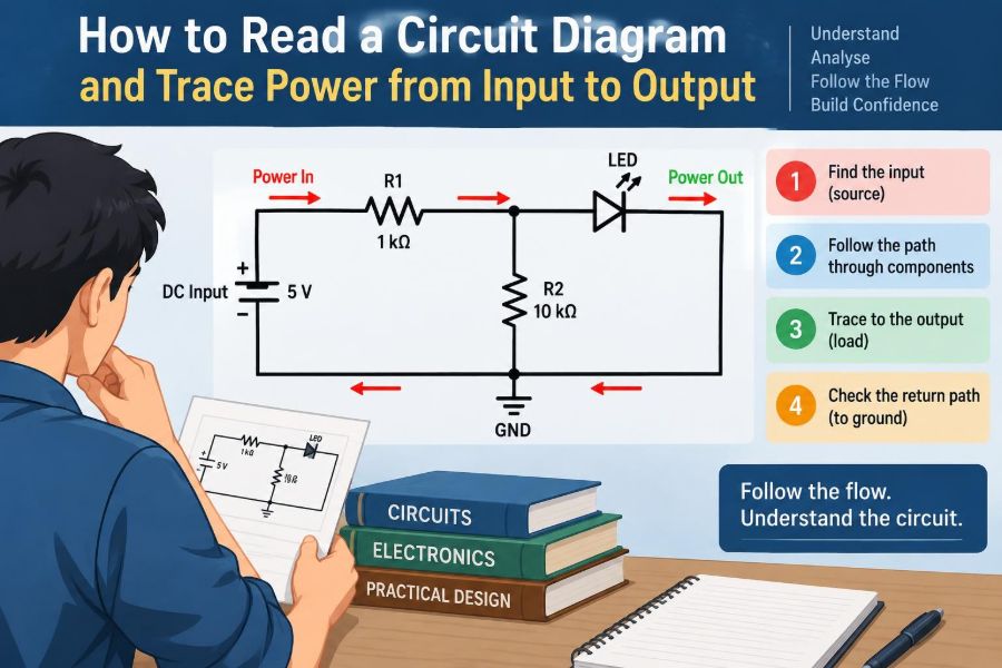

A device that will not turn on can make a circuit diagram look like a maze: lines cross, symbols are unfamiliar, and the page may contain several power rails with names that seem unrelated to the connector where power enters.
Yet the diagram is usually telling a practical story. Energy enters through a connector or battery, is protected and conditioned, converted into the voltages each circuit needs, switched or controlled, and finally delivered to loads such as processors, motors, LEDs, and sensors.
Reading that story is a foundational skill for design, troubleshooting, repair, and review. It helps you decide where to measure, what voltage to expect, and whether a missing output is caused by the source, protection, regulator, enable logic, or the load itself.
The goal is not to memorize every symbol at once. It is to develop a repeatable method for following power from input to output without being misled by page boundaries, net labels, or the physical appearance of the finished board.
🗺️ Treat the Diagram as a Functional Map
A schematic is a logical representation of a circuit, not a picture of its physical layout. Components placed near one another on the page are related electrically only when wires, labels, or connection markers say they are.
Start by asking one question: where does electrical energy enter? Then follow its path through each intentional stage. This approach is more reliable than trying to understand every part simultaneously.
Most power paths contain recognizable functions: entry, protection, filtering, conversion, distribution, control, and load. Finding these functions turns a dense schematic into manageable blocks.
🔋 Find the True Power Input
The input may be a barrel jack, USB connector, battery terminal, terminal block, backplane pin, or a named supply net arriving from another schematic sheet. Look for labels such as VIN, VBUS, BAT, DC_IN, +12V, or PWR_IN.
Do not assume the connector’s largest-looking pin is positive. Consult its pin labels and connector symbol. A battery connector may include a temperature-sense terminal; USB has data pins alongside power; an AC input may reach a rectifier before there is any defined positive DC rail.
For a hypothetical battery-powered board, the starting point might be a two-pin connector labeled BAT+ and BAT−. BAT− is often the circuit reference or ground, but confirm that it is actually connected to the intended ground net.
📚 Read the Title Block, Notes, and Sheet Structure
Before tracing wires, inspect the title block and sheet notes. They may identify the input range, the board revision, signal conventions, connector references, and special warnings about test conditions.
Multi-sheet designs commonly separate a power-entry page from regulator, processor, and peripheral pages. A sheet index or hierarchical block symbol can reveal where a rail continues next.
Revision matters. A measurement guide written for one board revision can point to a component that changed value, reference designator, or function in another revision.
🧭 Understand Direction Without Trusting Page Orientation
Many schematics place inputs on the left and outputs on the right, with positive supply rails near the top and ground near the bottom. This convention makes diagrams easier to scan, but it is not an electrical law.
A vertical regulator symbol may show input at the top and output at the bottom. A feedback network can point backward across the page. Use pin names, arrows, net labels, and component context—not visual direction alone—to determine the path.
When the route becomes confusing, mark the net name and follow every occurrence. A labeled connection can be electrically continuous even when the drawing spans several sheets.
🔗 Learn What Actually Makes a Connection
A continuous wire joining component pins is a connection. A junction dot where wires meet is also a connection. In many drawing styles, crossing lines without a dot are not connected.
Different schematic tools use different crossing conventions, so look at several known connections on the page before assuming what a crossing means. A short wire “hop” often indicates that one wire passes over another without joining.
Net labels create connections as well. Two wires labeled +3V3 are normally the same electrical net even if no visible wire runs between them. A port or off-page connector serves the same purpose across sheets.
🏷️ Use Net Names as Your Navigation System
Net names are often the fastest way to trace power. Typical examples include VIN, VPROT, +5V, +3V3, VCORE, AVDD, and VREF. The names hint at voltage, stage, or intended use, though they must not replace verification.
A name such as +5V usually expresses design intent, not proof that the measured rail is exactly 5 V at all times. Load current, regulation tolerance, switching ripple, startup behavior, and faults all affect the real measurement.
Search every instance of a net in the schematic software or PDF. This quickly identifies its source, all loads, test points, decoupling capacitors, and any places where it is switched or isolated.
⏚ Establish the Return Path
Power flow is incomplete without a return path. Conventional current is often described as leaving the positive source terminal, passing through the load, and returning through ground or the negative terminal. Electrons move in the opposite direction, but either viewpoint requires a closed loop.
Ground symbols can represent several distinct nets: protective earth, chassis ground, digital ground, analog ground, power ground, or an isolated secondary return. They may be directly connected, linked through a component, or intentionally separate.
A regulator can show a correct voltage at its output pin and still fail to power a load if the return connection is broken. Whenever you trace a positive rail, identify its corresponding return.
🛡️ Recognize Input Protection Stages
Immediately after the input, look for components intended to survive common mistakes and disturbances. These may include fuses, resettable fuses, transient-voltage suppressors, reverse-polarity protection, surge limiters, and electromagnetic-interference filters.
A fuse is generally in series with the incoming rail. A transient suppressor diode is commonly connected from the rail to the return, where it can clamp short-duration overvoltage events. These positions reveal their functions even before every part number is known.
Protection parts can themselves interrupt power. A blown fuse, open connector contact, or failed reverse-protection device can make all downstream rails disappear.
🔀 Follow Series Components and Branches
A series component lies directly in the current path: the rail must pass through it to reach the next point. Examples include fuses, switches, ferrite beads, current-sense resistors, ideal-diode controllers, and MOSFETs.
A branch occurs when one net divides into multiple paths. One branch may feed a regulator, another a charging circuit, and another a monitoring divider. A fault in one branch may not explain a failure in another.
At every branch, ask: which route leads toward the output I am investigating, and which routes are parallel consumers? This prevents following a nearby but irrelevant path.
🧲 Distinguish Resistors, Ferrite Beads, and Inductors
These components can all appear in series with a rail, but they serve different purposes. A resistor intentionally drops voltage or senses current. A ferrite bead mainly impedes high-frequency noise while passing DC with low resistance. An inductor stores energy and is central to many switching regulators.
| Component | Common power-path role | Useful tracing clue |
|---|---|---|
| Resistor | Current limiting, sensing, voltage division | Value is marked in ohms; a substantial voltage drop may be intentional |
| Ferrite bead | Noise isolation between rail domains | Often connects a main rail to a locally filtered rail |
| Inductor | Energy transfer in a switching converter | Usually near a switching IC, diode or MOSFET, and capacitors |
Do not treat a ferrite bead as a conventional fuse. It can fail, but its intended function is filtering rather than overcurrent protection.
⚙️ Identify the Regulator Type
A regulator changes or stabilizes voltage. A linear regulator usually has input, output, ground, and perhaps enable or adjustment pins. It reduces voltage by dissipating excess energy as heat, so its output cannot normally exceed its input.
A switching regulator transfers energy through a rapidly switched transistor, an inductor, capacitors, and often a diode or synchronous transistor. It can step voltage down, step it up, or invert polarity depending on topology.
Recognizing the regulator prevents impossible expectations. A buck converter normally generates a lower output from a higher input; a boost converter can create a higher rail from a lower input.
📐 Decode a Linear Regulator Path
For a typical linear regulator, trace from VIN to the input pin, then from the output pin to the output capacitor and named rail. The ground pin or exposed thermal pad may be essential to both electrical reference and heat removal.
Many linear regulators require capacitors within specified ranges and with suitable equivalent series resistance. The schematic shows that these capacitors are part of the regulator system, not optional decorations.
If the output is absent, compare input voltage, enable state, ground continuity, and output voltage. A shorted output can make the regulator limit current or enter thermal shutdown.
🌊 Decode a Switching Regulator Path
A switching stage often looks less intuitive because its switching node is not a steady DC output. In a buck converter, the switching node pulses between voltage levels, then the inductor and output capacitor smooth the transferred energy into a lower DC rail.
Trace the regulated output after the inductor, not at the noisy switch node. The feedback divider usually senses the clean output rail and returns a scaled voltage to the controller’s feedback pin.
Measurement requires care. A multimeter may show an average voltage, while an oscilloscope can reveal ripple, oscillation, or switching activity. Probe technique and grounding can significantly affect what an oscilloscope displays.
📊 Read Feedback Networks Without Losing the Main Path
A feedback network tells a regulator how much output voltage it is producing. It commonly consists of two resistors: one from output to the feedback pin and one from the feedback pin to ground or a reference node.
This network is a control path, not the main high-current power path. Separating these roles makes dense regulator sections easier to read.
Adjustable regulators set output according to an internal reference and the resistor ratio, but do not calculate an expected voltage unless the device datasheet and all relevant connections are available. Some controllers use compensation networks that look similar but have a different purpose.
🎛️ Check Enable, Shutdown, and Power-Good Pins
A regulator with valid input may deliberately hold its output off. Pins labeled EN, ENABLE, SHDN, ON, PGOOD, RESET, or POWER_OK control or report startup behavior.
An enable pin may be tied directly high, pulled up through a resistor, controlled by a microcontroller, or driven by a voltage supervisor. If it is below its required threshold, the regulator may remain off despite a healthy input.
Power-good is usually an output status signal, often open-drain, rather than a power source. Confusing it with a supply rail is a common tracing mistake.
⏳ Understand Power Sequencing
Complex equipment may require rails to start in a particular order. A processor, memory device, or analog converter can have separate core, input/output, and reference supplies with constraints on ramp timing.
Sequencing circuits use supervisors, resistor-capacitor delays, logic gates, or dedicated power-management ICs. They ensure that one rail enables only after another has reached an acceptable voltage.
When troubleshooting, a missing late-stage rail may be a symptom rather than the first fault. Trace backward to the rail or control signal that grants permission for it to start.
🔌 Recognize Load Switches and Power MUXes
Not every voltage change comes from a regulator. A load switch is commonly a MOSFET-based device that turns an existing rail on or off for a subsystem. Its input and output may have nearly the same nominal voltage.
A power multiplexer, or power MUX, selects between sources such as USB and a battery. Ideal-diode circuits similarly control current direction with low voltage loss compared with an ordinary diode.
Look for pins such as IN, OUT, EN, ILIM, FLAG, SEL, or STAT. These parts explain why a rail can be present near the source but absent at a removable module or peripheral.
🔍 Tell a Power Path from a Signal Path
Power rails often connect to many pins, bypass capacitors, and broad subsystem blocks. Signal paths more often run point-to-point between logic pins and include series resistors, pull-ups, buses, or labeled communications lines.
A wire called SCL, TX, PWM, FB, or ALERT is usually not intended to deliver load power, even if it happens to be near a regulator. Conversely, an EN line can determine whether power is delivered without carrying meaningful load current itself.
Classifying each line as source, return, power rail, control, feedback, or status keeps the trace organized.
🧱 Follow Power Through Hierarchical Blocks
Large schematics use blocks for subsystems such as “Processor,” “Motor Driver,” or “Display Module.” Pins on the block represent connections into another sheet or a separately designed module.
When a rail enters a block, note its exact net name and the pin label. Then open the referenced sheet and find that same name. Do not infer that a generic block title means every internal circuit uses the same supply.
A processor block might accept +3V3, +1V8, and VBAT simultaneously. Each rail can have a different source, startup condition, and fault behavior.
🧮 Use Component Reference Designators Wisely
Reference designators identify physical components: R for resistor, C for capacitor, D for diode, Q for transistor, L for inductor, U for integrated circuit, and F for fuse in many conventions. Exact naming practices vary by organization.
They let you correlate the schematic with a bill of materials, PCB layout, assembly drawing, or board silkscreen. For troubleshooting, “measure both sides of F1” is far more actionable than “check the fuse area.”
Still, the prefix alone does not prove function. A diode can provide reverse protection, clamping, rectification, or signal steering; context determines its role.
🧪 Use Test Points and Decoupling Capacitors as Clues
Test points are intentional places to access important nets. A point labeled TP3V3 or TP_VIN often provides a convenient, low-risk location to verify a rail, though you should still confirm its net label on the schematic.
Decoupling capacitors connect between a supply rail and return close to IC power pins. Their presence helps identify which rail feeds a chip, especially when the power pins are hidden in a schematic symbol.
They also explain why a rail may remain charged briefly after power is removed. Stored energy in capacitors can affect resistance measurements and make a fault appear intermittent.
📏 Choose Measurements That Answer a Question
Measurement is most effective when each reading tests a specific hypothesis. If a rail is missing, begin with the source and move stage by stage: input connector, protection output, regulator input, regulator output, switch output, and load-side test point.
- Set a known reference point, usually the relevant circuit ground.
- Measure the intended input voltage.
- Measure before and after each series element.
- Check regulator enable or control conditions when input is present.
- Measure the output before and after any load switch or bead.
A voltage drop across a closed switch or fuse should normally be small under normal conditions. A large drop suggests resistance, excessive current, or a component that is not truly conducting.
⚠️ Make Measurements Safely
Live circuits can be damaged by a slipped probe, especially around fine-pitch IC pins, high-current supplies, mains-connected equipment, and switching nodes. Use insulated probes, secure the board, and avoid bridging adjacent pins.
Never use resistance or continuity mode on an energized circuit. Remove power and allow capacitors to discharge before checking resistance. Some products retain hazardous energy after disconnection, so manufacturer service information and appropriate safety procedures matter.
For mains-powered or high-energy systems, ordinary bench techniques may be insufficient. Isolation requirements, probe ratings, exposed conductive parts, and fault energy must be evaluated by someone qualified for that equipment.
🧯 Check for Shorts Before Forcing Power
With power removed, resistance from a rail to ground can provide a clue, but it is not a definitive diagnosis. Low-voltage, high-current rails often have naturally low resistance because their loads contain many transistor structures and capacitors.
More useful questions are whether the resistance is unexpectedly different from a known-good board, whether it changes as capacitors charge from the meter, and whether there is an obvious damaged component on that net.
Do not inject arbitrary voltage or current into a rail. Controlled current-limited injection can be a specialist diagnostic technique, but the safe voltage, current, and injection point depend on the circuit and its connected devices.
🧠 Separate a Fault from a Normal Operating State
A rail that reads 0 V is not always defective. It may be switched off in standby, enabled only during charging, active only after firmware boots, or controlled by an external interlock.
Read surrounding labels and notes for states such as SLEEP, RUN, ALWAYS_ON, or USB_PRESENT. Check whether the expected source is connected and whether the board is being tested in the operating mode assumed by the schematic.
Similarly, a voltage that appears lower than expected may be a deliberately current-limited supply under load, a battery near depletion, or the average reading of a pulsed signal rather than a failed regulator.
🧩 Work Through a Simple Example
Consider a hypothetical portable instrument powered by a 9 V adapter. The diagram shows DC_IN passing through F1, then a reverse-polarity MOSFET, creating a net named VPROT. VPROT feeds a 5 V buck regulator, and the 5 V rail feeds a 3.3 V linear regulator for logic.
To trace power to a microcontroller, follow this chain: adapter positive → F1 → reverse-protection MOSFET → VPROT → buck input → buck output capacitor on +5V → 3.3 V regulator input → +3V3 output capacitor → microcontroller supply pins.
If +3V3 is absent while +5V is correct, the adapter and buck regulator are less likely to be the immediate cause. Check the linear regulator’s enable, input, ground, output loading, and any load switch between +3V3 and the microcontroller.
📝 Build a Rail Trace Worksheet
For a complicated board, record the path rather than relying on memory. A compact worksheet turns schematic reading into a repeatable diagnostic process.
- Rail: the net being investigated, such as +3V3.
- Source: connector, battery, or upstream regulator.
- Series path: fuse, switch, bead, MOSFET, and connector pins.
- Control conditions: enable, power-good, interlock, or sequencing dependency.
- Expected observation: nominal voltage and operating state.
- Loads: ICs, modules, and downstream branches.
This record is also useful during design review. It reveals undocumented dependencies and makes another engineer’s troubleshooting work much faster.
🚫 Avoid the Most Common Reading Errors
Several mistakes repeatedly send readers down the wrong path:
- Assuming crossed wires connect without checking the schematic’s junction convention.
- Following a visual line across a page while ignoring a net label that changes the route.
- Treating every ground symbol as the same node.
- Measuring a switching node and calling it a DC output.
- Ignoring enable, fault, and sequencing signals.
- Assuming a component is faulty because a downstream rail is absent, without verifying its input.
- Using an unpowered resistance reading as conclusive proof of a short.
The correction is simple but disciplined: verify each stage’s input, condition, and output in order.
🛠️ Match the Schematic to the Physical Board
Once the logical route is clear, use reference designators and PCB markings to locate components. Board layout may place a regulator, inductor, and capacitors close together for electrical performance even when they are far apart on the schematic page.
Follow copper cautiously. Inner layers can hide connections, and large planes may join points that look separate from the board surface. The schematic remains the authority for intended connectivity; the layout and board reveal where to probe.
Use test pads or component ends with adequate spacing whenever possible. Avoid probing directly on tiny IC pins unless there is no safer option.
📖 Know When the Datasheet Is Necessary
A schematic tells you how a part is connected, but the datasheet explains what those connections require. This is especially true for regulators, power-path controllers, battery chargers, supervisors, and protection ICs.
Consult the datasheet when pin behavior is unclear, when an enable threshold matters, when a fault pin is open-drain, or when a regulator’s compensation and capacitor requirements affect operation.
Use the exact part number when possible. Devices with similar names or packages can have different pinouts, absolute maximum ratings, and startup behavior.
✅ A Repeatable Input-to-Output Method
When facing an unfamiliar circuit diagram, use the same sequence every time:
- Find the input source and its return path.
- Identify protection and every series element.
- Follow net names across pages and branches.
- Locate each conversion, switching, or selection stage.
- Check the enable and sequencing conditions of each active stage.
- Identify the named output rail and its loads.
- Choose safe points to verify source, stage input, and stage output.
This method works for a simple LED board and scales to multi-rail embedded hardware. The details change, but the electrical logic remains: source, path, control, load, and return.
🏁 The Core Principle of Power Tracing
Reading a power schematic is less about recognizing every symbol instantly than about asking structured questions. Where does the energy originate? What can interrupt, alter, or authorize it? Where does it go, and how does it return?
Trace one rail at a time, distinguish the high-current path from its control and feedback signals, and verify each stage before blaming the next one. A diagram becomes understandable when you translate it into a sequence of physical functions rather than a collection of lines.
The most reliable diagnosis follows power from a verified source through every protection, conversion, control, and distribution stage to a verified load and return path. With that habit, even a crowded multi-sheet schematic becomes a practical map instead of a puzzle. 🔌🧭