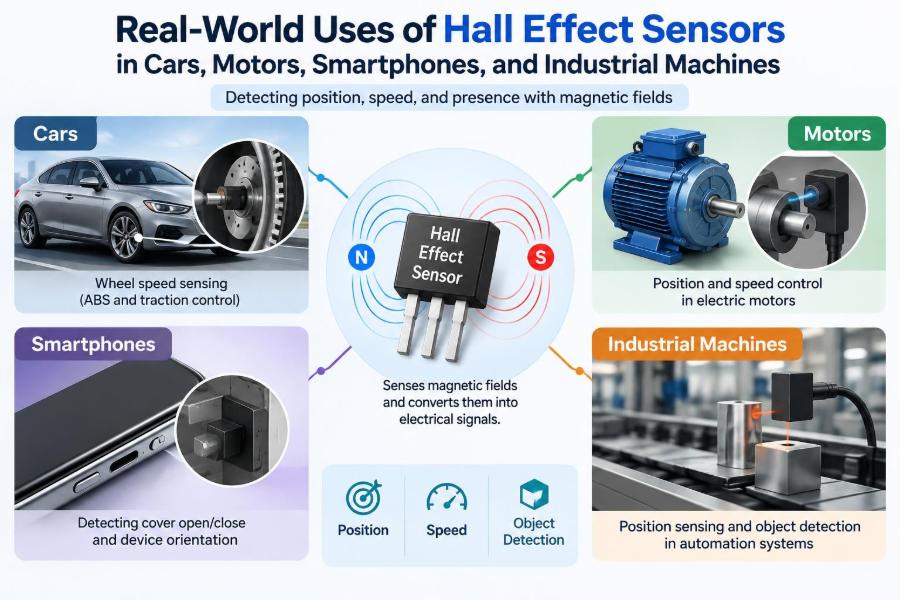

You press the accelerator, and the car responds smoothly. Your phone knows when a protective cover has closed. A factory conveyor stops before a moving fixture reaches its mechanical limit. These small actions feel ordinary because the sensing hardware behind them is usually invisible.
In many of these systems, a Hall effect sensor is doing a quiet but essential job: detecting a magnetic field and converting that detection into an electrical signal. It can tell a controller that something is nearby, moving, rotating, or positioned at a known point—often without physical contact.
That contactless operation is a major reason Hall sensors appear in vehicles, motors, consumer electronics, and industrial equipment. They can work through sealed housings, tolerate repeated motion, and provide useful digital or analog information to a control system.
Understanding where they are used also makes their limitations clearer. A Hall sensor is not simply a universal “magnet detector”; correct magnet choice, alignment, air gap, electrical protection, and signal interpretation all matter.
🧲 The Hall Effect in Plain Language
The Hall effect occurs when electric current flows through a conductive or semiconductor material while a magnetic field passes across it. Moving charge carriers are pushed sideways, producing a small voltage across the material. This is called the Hall voltage.
Integrated Hall sensors contain the Hall element plus electronics that amplify, compensate, compare, and format that tiny signal. The final output may be a simple on/off switch, a changing analog voltage, a digital pulse train, or a communicated position value.
🔍 Why Contactless Sensing Changes Machine Design
A mechanical switch needs a moving contact or lever. Over many cycles, that part can wear, bounce, corrode, or become obstructed by dust and oil. A Hall sensor can detect a magnetic field with no touching parts between sensor and target.
This does not mean it never fails. Magnets can be misplaced, wiring can be damaged, and electronics can be exposed to excessive heat or voltage transients. But removing mechanical contact often improves service life and allows sensors to sit inside sealed enclosures.
⚙️ The Main Types of Hall Effect Sensors
Choosing the right category starts with the information the system needs. A door-open detector needs a different sensor from a steering-angle system or an electric-motor controller.
| Sensor type | Typical output | Useful for |
|---|---|---|
| Digital switch | On/off state | Door, cover, end-stop, home position |
| Latch | State changes with opposite magnetic poles | Rotating magnet detection |
| Linear Hall sensor | Voltage proportional to field | Displacement and current measurement |
| Angle sensor | Angular position data | Throttle, pedals, steering, rotary controls |
Many modern devices combine sensing elements and diagnostics in one package. Their output can be more informative than a raw voltage, but that also means the controller must understand fault states and communication behavior.
🚦 Digital Switches, Latches, and Linear Outputs
A digital Hall switch changes output when magnetic field strength crosses a designed threshold. It is suitable when the question is simply, “Is the magnet present?” Built-in hysteresis usually prevents rapid output chatter when the magnet sits near the threshold.
A latching sensor responds differently to north and south magnetic poles. It may turn on when one pole arrives and remain on until the opposite pole appears. This makes it useful with alternating-pole ring magnets used in rotation sensing.
Linear devices preserve field information over a specified operating range. They are used when direction or magnitude matters, although their output needs careful calibration and filtering.
🚗 Crankshaft Position in Internal-Combustion Engines
An engine controller must know crankshaft position and speed to schedule ignition and fuel injection. Depending on the vehicle design, a Hall sensor may read teeth, slots, or a magnetic target on a rotating wheel.
Each transition becomes timing information. A deliberately missing tooth or another reference feature lets the controller identify a known crankshaft position rather than merely count speed pulses.
Some engines use other sensing technologies, including variable-reluctance sensors. The specific implementation varies, but the system requirement is the same: accurate timing across vibration, temperature changes, electrical noise, and a broad speed range.
🌀 Camshaft Synchronization and Cylinder Identification
Crank position tells the controller where the crankshaft is, but a four-stroke engine also needs to distinguish between cycles that occur at the same crank angle. A camshaft position signal provides that synchronization information.
A Hall-effect cam sensor commonly detects a shaped target or magnet on the camshaft. Together, crank and cam signals help the controller identify the correct cylinder event for sequential fuel injection, variable valve timing management, and diagnostic checks.
🛞 Wheel-Speed Sensing for Vehicle Control
Wheel-speed data supports anti-lock braking, traction control, stability systems, and speed display functions. Sensors mounted near a wheel bearing or tone ring generate pulses as encoded magnetic regions or teeth pass by.
The control unit compares wheel behavior. If one wheel decelerates unusually quickly under braking, the system can reduce brake pressure at that wheel to help prevent lockup. This is a control decision based on multiple inputs, not a promise that every skid can be avoided.
Road debris, damaged encoder rings, excessive bearing play, and corroded connectors can all degrade this measurement.
🧭 Steering-Angle and Pedal Position Feedback
Modern vehicles need reliable position feedback from rotating parts. Hall-based angle sensors can measure the orientation of a magnet attached to a shaft, often without gears that would introduce backlash and wear.
Applications include steering-angle measurement, accelerator pedal travel, brake-pedal position, gear-selector position, and electronic throttle bodies. In safety-relevant systems, designers commonly use redundant sensing paths with different signal relationships so the controller can detect disagreement.
Redundancy does not eliminate every fault; it creates an opportunity to recognize implausible data and move to a safer operating mode.
🔋 Current Measurement in Electric and Hybrid Vehicles
Hall sensors can measure current by detecting the magnetic field around a conductor. This avoids putting the sensor’s measurement element directly in the high-current path, providing galvanic isolation between the power circuit and low-voltage electronics in many arrangements.
Battery-management systems, traction inverters, DC-DC converters, and charging equipment need current information for control and protection. The measured value may help estimate battery state, regulate motor torque, or identify overcurrent conditions.
Accuracy depends on conductor geometry, magnetic-core design where used, temperature behavior, offset drift, and calibration. Nearby current-carrying cables can also influence poorly designed layouts.
🚪 Magnetic Door, Hood, and Tailgate Detection
A compact Hall switch and magnet make a robust open/closed detector. The sensor can remain inside a protected body panel while the magnet is mounted on the moving door, hood, liftgate, or charging flap.
This approach is especially useful where a protruding mechanical plunger would be exposed to water, dirt, or misalignment. The controller can activate interior lighting, issue a dashboard warning, change alarm behavior, or prevent an unsafe machine sequence.
🌡️ Automotive Conditions Are Harsh
Vehicle sensors experience vibration, moisture, road salt, oil, thermal cycling, and electrical disturbances caused by switching loads. A sensor that works neatly on a bench may be unreliable if its connector seal, mounting bracket, cable routing, or transient protection is inadequate.
Automotive Hall devices are therefore selected as part of a system, not as isolated parts. The magnet must stay attached, the target geometry must remain stable, and the software must handle missing or implausible signals.
🛵 Commutation in Brushless DC Motors
A brushless DC motor needs electronics to energize its stator windings in the correct sequence. Hall sensors placed around the stator can report rotor magnet position. The controller uses those signals to decide which winding phases should be driven.
In a simple three-sensor arrangement, the output pattern indicates a sector of the electrical rotation. This is enough for reliable startup and low-speed torque in many fans, pumps, e-bikes, tools, and small actuators.
The Hall sensor is not creating torque. It provides rotor-position feedback so the power electronics can create a rotating magnetic field at the right time.
⚡ Why Motor Timing Affects Torque and Efficiency
If commutation occurs too early or too late, the stator field is poorly aligned with the rotor. The motor may lose torque, draw unnecessary current, produce more noise, or run roughly at low speed.
Correct Hall placement and controller timing are therefore linked. Manufacturers may calibrate sensor placement mechanically or compensate for known offsets in firmware. A replacement motor controller should not assume that every motor’s Hall sequence and phase wiring are identical.
🌬️ Fans, Pumps, and Everyday Appliances
Computer cooling fans often use Hall sensing to detect rotor position and control commutation. A fan may also generate a tachometer output so another circuit can verify that it is actually turning.
Similar principles appear in circulation pumps, refrigerator fans, air purifiers, power tools, and compact blowers. In these products, a Hall sensor can provide a reliable electronic alternative to brush commutators, which physically switch current in a brushed motor.
🏭 Encoder-Like Rotation Measurement in Industrial Machines
Industrial equipment often needs speed or count information rather than full high-resolution angular position. A rotating wheel with magnets or alternating magnetic poles can create pulses at a Hall sensor.
Counting pulses estimates movement; measuring pulse frequency estimates speed; comparing two phase-shifted channels can reveal direction. This is useful for conveyors, packaging machines, rollers, agitators, and material-handling equipment.
Resolution is limited by the number of magnetic transitions and the quality of the sensing arrangement. A Hall-based pulse sensor should not automatically be treated as interchangeable with a precision optical encoder.
🏠 Home Position and End-of-Travel Detection
Many machines need one dependable reference point after power-up. A magnet mounted on a carriage, shaft, or moving arm can trigger a Hall sensor at the home position, allowing the controller to establish a known coordinate.
Examples include printer carriages, motorized valves, robotic axes, sliding guards, and automatic dispensers. The sensor may also act as a non-contact end-of-travel indicator, but motion systems still need appropriate mechanical stops and safety design.
🤖 Robotics and Automated Handling
Robots use Hall sensors in grippers, joints, mobile platforms, tool changers, and docking systems. They can confirm that a gripper is closed, determine a rotary actuator’s sector, or sense that a magnetic fixture is present.
For collaborative or safety-critical machinery, that simple confirmation is only one layer of the overall design. The required architecture depends on the hazard, machine function, applicable requirements, and the diagnostic coverage of the entire system.
📱 Smartphones Detect Covers and Accessories
In a smartphone or tablet, a Hall sensor can detect a magnet embedded in a folio cover. Closing the cover can turn off or lock the display; opening it can wake the screen. The sensor is small, consumes little power in suitable modes, and works without an exposed mechanical button.
Some devices also use magnetic detection to identify accessories or establish alignment. The exact behavior is product-specific, and a magnetically attached accessory may use other technologies in addition to Hall sensing.
🧲 Tablets, Laptops, and Foldable Devices
Laptop lids and detachable keyboards can use magnetic sensing to determine whether parts are closed, attached, or correctly positioned. A foldable device may use several sensors and magnets to infer hinge state or screen orientation.
These applications show an advantage of magnetic sensing: the sensor can be hidden behind plastic, glass, or a sealed case. However, external magnets can sometimes cause unintended behavior if they are strong enough and placed close enough to the sensor.
🎮 Controllers, Knobs, and Contactless Input
Hall-effect joysticks and triggers use magnet position rather than a sliding resistive track. In principle, this avoids the wear associated with a potentiometer’s wiper moving over a resistive element.
A Hall-based thumbstick can still feel poor if its mechanical centering springs, bearings, magnet mounting, or calibration are poor. Contactless sensing addresses one wear mechanism; it does not automatically solve every source of drift or mechanical looseness.
📏 Measuring Position with a Moving Magnet
For linear position sensing, a magnet moves relative to a Hall sensor. Field strength or field direction changes with position, and electronics translate that change into an output. The useful travel range depends heavily on magnet shape, orientation, and the sensor’s designed measurement range.
A nearby steel bracket can distort the magnetic field. So can tilt, lateral offset, and changes in the air gap. Engineers often validate the full mechanical tolerance stack, rather than calibrating only one ideal sample.
🧮 Measuring Angle with Two Magnetic Axes
Angle sensors often measure two perpendicular components of a rotating magnetic field. From these components, the device can calculate angular position across a turn or, in some designs, over a specified travel range.
This is more robust than trying to infer angle from one changing field magnitude alone, because magnitude can change with distance. Still, the magnet must be centered and positioned according to the device guidance for the stated accuracy to be meaningful.
🔌 Signal Interfaces: Voltage, Pulses, and Digital Buses
A Hall sensor’s output must match the controller input. Simple devices may use an open-drain or open-collector output that requires a pull-up resistor. Others provide push-pull logic, analog ratiometric voltage, pulse-width information, or a digital communication interface.
Ratiometric analog output means the signal scales with the supply voltage, allowing an analog-to-digital converter using the same reference to reduce sensitivity to supply variation. It does not remove errors from temperature, magnetic misalignment, or noise.
🧰 Selecting a Sensor Is More Than Choosing Sensitivity
Datasheets list operating field thresholds or ranges, but selection also requires a mechanical and electrical view of the application. The sensor must operate across the weakest expected magnetic field and avoid unwanted triggering at the strongest field.
- Define required information: presence, speed, direction, angle, displacement, or current.
- Calculate worst-case air gap, alignment error, and temperature effects.
- Check supply voltage, output type, timing, and controller compatibility.
- Consider vibration, contamination, enclosure material, and cable length.
- Plan for diagnostics if a wrong reading could create a hazard.
A prototype with a hand-held magnet is useful for learning, but it is not proof that a production arrangement has sufficient margin.
📐 Magnet Choice and Mechanical Alignment
Magnet material, dimensions, magnetization direction, and pole arrangement determine the field that reaches the sensor. Stronger is not always better: a sensor can saturate or switch too early if the field is excessive.
Alignment matters just as much. A few millimeters of separation or sideways offset can change field strength substantially in a compact design. Designers should evaluate manufacturing tolerance, mounting movement, aging considerations, and nearby ferromagnetic material.
🛡️ Noise, Wiring, and Electrical Protection
Long sensor cables can pick up interference from motor phases, relays, solenoids, and switching power supplies. Twisted conductors, sensible grounding strategy, shielding where appropriate, input filtering, and physical separation from high-current paths can improve signal integrity.
Protection against reverse battery connection, electrostatic discharge, voltage spikes, and load-dump-like vehicle transients is application dependent. A clean bench supply rarely reproduces the electrical environment of a running machine or vehicle.
🧪 Testing Beyond the Bench
Useful tests include slow movement through the full travel, maximum expected speed, supply-voltage variation, elevated and low temperatures, vibration, and deliberate misalignment. For rotating systems, inspect pulse spacing and state transitions with an oscilloscope or logic analyzer.
Test faults too: disconnect the sensor, short an output where safe to simulate, weaken the magnet path, and introduce plausible intermittent wiring movement. The goal is not merely to confirm normal operation; it is to understand how the system recognizes abnormal operation.
⚠️ Common Design and Troubleshooting Mistakes
One common mistake is confusing a unipolar switch, bipolar latch, and linear sensor. Their response to field direction and threshold is different, so a circuit can appear dead simply because the wrong pole or wrong device type is used.
- Ignoring the pull-up resistor required by an open-drain output.
- Mounting the sensor at an unverified distance from the magnet.
- Using a steel fastener or bracket that redirects the field unexpectedly.
- Assuming a pulse signal proves correct direction or absolute position.
- Replacing a vehicle sensor without checking connector pinout, target condition, and fault codes.
Diagnosis should include supply voltage, ground quality, output waveform, target movement, and mechanical air gap—not only a continuity test.
🔄 Hall Sensors Compared with Other Sensing Methods
Optical sensors can provide high resolution, but dust, oil, or condensation may obstruct their path. Inductive proximity sensors detect metal targets without magnets and are common in industry, though they do not generally provide the same magnetic-pole information.
Resolvers and some encoders offer high robustness or precision for demanding motion control, often with greater size, cost, or interface complexity. Potentiometers are simple and can provide absolute position, but their sliding contacts wear. The best choice depends on the required accuracy, environment, cost, and failure behavior.
🧠 The Core Principle: Field Information Becomes Control
The real value of a Hall effect sensor is not the magnetic field by itself. It is the useful decision built from that field: fire an injector at the right moment, commutate a motor phase, detect a closed lid, stop an axis at home, or estimate current in a power system.
Good designs connect three disciplines: magnetic geometry, electronics, and software. When any one is overlooked, a seemingly simple sensor can become an intermittent system problem. When they are designed together, Hall sensing offers compact, durable feedback across an enormous range of real machines.
Hall effect sensors succeed because they turn motion, position, and current into contactless electrical information that a controller can act on reliably—provided the magnetics, mechanics, wiring, and diagnostics are engineered as one system. From the wheel of a car to the hinge of a tablet and the rotor of a motor, that quiet measurement enables useful control every day. 🧲⚙️📱