Nodes
A node is a section of a circuit which connects components to each other. All of the current entering a node must leave a node, according to Kirchhoff’s Current Law. Every point on the node is at the same voltage, no matter how close it is to each component, because the connections between components are perfect conductors. This voltage is called the node voltage, and is the voltage difference between the node and an arbitrary reference, the ground point. The ground point is a node which is defined as having zero voltage. The ground node should be chosen carefully for convenience. Note that the ground node does not necessarily represent an actual connection to ground, it is just a device to make the analysis simpler. For example, if a node has a voltage of 5 Volts, then the voltage drop between that node and the ground node will be 5 Volts.
Note that in real circuits, nodes are made up of wires, which are not perfect conductors, and so the voltage is not perfectly the same everywhere on the node. This distinction is only important in demanding applications, such as low noise audio, high speed digital circuits (like modern computers), etc. If we look at how a particular circuit functions an engineer might be able to select check points that are diametrically opposite of each other, this signifies two points of current crossing over to another point this can be another method in testing a circuit to determine how nodes work.
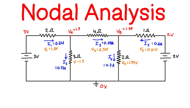
Nodal Analysis
Nodal analysis is a formalized procedure based on KCL equations. Steps:
- Identify all nodes.
- Choose a reference node. Identify it with reference (ground) symbol. A good choice is the node with the most branches, or a node which can immediately give you another node voltage (e.g., below a voltage source).
- Assign voltage variables to the other nodes (these are node voltages.)
- Write a KCL equation for each node (sum the currents leaving the node and set equal to zero). Rearrange these equations into the form AV1+BV2=C (or similar for equations with more voltage variables.)
- Solve the system of equations from step 4. There are a number of techniques that can be used: simple substitution, Cramer’s rule, the adjoint matrix method, etc.
Complications in Nodal Analysis
- Dependent Current Source Solution: Write KVL equations for each node. Then express the extra variable (whatever the current source depends on) in terms of node voltages. Rearrange into the form from step 4 above. Solve as in step 5.
- Independent Voltage Source Problem: We know nothing about the current through the voltage source. We cannot write KCL equations for the nodes the voltage source is connected to. Solution: If the voltage source is between the reference node and any other node, we have been given a ’free’ node voltage: the node voltage must be equal to the voltage source value! Otherwise, use a ’super-node’, consisting of the source and the nodes it is connected to. Write a KCL equation for all current entering and leaving the super-node. Now we have one equation and two unknowns (the node voltages). Another equation that relates these voltages is the equation provided by the voltage source (V2-V1=source value). This new system of equations can be solved as in Step 5 above.
- Dependent Voltage Source Solution: Same as an independent voltage source, with an extra step. First write a super-node KCL equation. Then write the source controlling quantity (dependence quantity?) in terms of the node voltages. Rearrange the equation to be in the AV1+BV2=C form. Solve the system as above.


