Overview
A counter is a device that generates some patterned binary value depending on a clock or some other pulsed input. There are three simple types of counters ripple and synchronous.
Types of Counters
Ring Counters
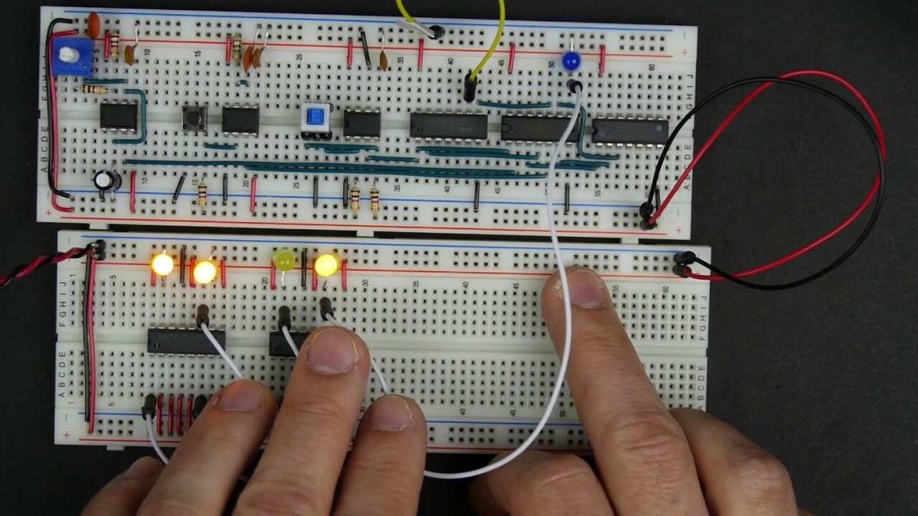
If the output of a shift register is fed back to the input. a ring counter results. The data pattern contained within the shift register will recirculate as long as clock pulses are applied. For example, the data pattern will repeat every four clock pulses in the figure below. However, we must load a data pattern. All 0’s or all 1’s doesn’t count. Is a continuous logic level from such a condition useful?
We make provisions for loading data into the parallel-in/ serial-out shift register configured as a ring counter below. Any random pattern may be loaded. The most generally useful pattern is a single 1.
Loading binary 1000 into the ring counter, above, prior to shifting yields a viewable pattern. The data pattern for a single stage repeats every four clock pulses in our 4-stage example. The waveforms for all four stages look the same, except for the one clock time delay from one stage to the next. See figure below.
The circuit above is a divide by 4 counter. Comparing the clock input to any one of the outputs, shows a frequency ratio of 4:1. How may stages would we need for a divide by 10 ring counter? Ten stages would recirculate the 1 every 10 clock pulses.
An alternate method of initializing the ring counter to 1000 is shown above. The shift waveforms are identical to those above, repeating every fourth clock pulse. The requirement for initialization is a disadvantage of the ring counter over a conventional counter. At a minimum, it must be initialized at power-up since there is no way to predict what state flip-flops will power up in. In theory, initialization should never be required again. In actual practice, the flip-flops could eventually be corrupted by noise, destroying the data pattern. A ”self-correcting” counter, like a conventional synchronous binary counter would be more reliable.
The above binary synchronous counter needs only two stages, but requires decoder gates. The ring counter had more stages, but was self-decoding, saving the decode gates above. Another disadvantage of the ring counter is that it is not ”self-starting”. If we need the decoded outputs, the ring counter looks attractive, in particular, if most of the logic is in a single shift register package. If not, the conventional binary counter is less complex without the decoder.
The waveforms decoded from the synchronous binary counter are identical to the previous ring counter waveforms. The counter sequence is (QA QB) = (00 01 10 11).
Ripple Counters
Ripple counters are the simplest type of counters. They are nothing more than toggle flip flops connected in a chain to divide each other’s output frequency by two. The result is a binary count. They are called ripple counters because the new count ripples through them. The major disadvantage of ripple counters is that because of new count ”rippling” through the flip flops all the bits of the count arrive at different times.
Synchronous Counters
Synchronous counters are simple state machines made out of flip flops and logic gates. They have two parts, a register made out of flip flops and a decoder made out of logic gates. A register is a simple group of flip flops that are all clocked at the same time. In this way they can hold the counters output value until the next clock cycle. The decoder decodes the current count and generates the correct value for the next count to the flop flops. For example in a simple up counter the decoder would always output the current count plus one. The major advantage of Synchronous Counters is that all the bits of their output change at the same time.


