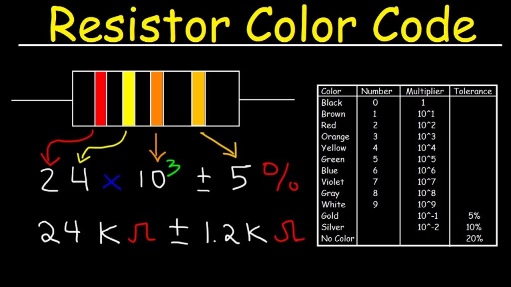
A process called colour coding is used to determine the value of resistance for a resistor, just as shown in the above figure. A resistor is coated with four color bands where each colour determines a particular value. The below table shows a list of values which each colour indicates.
| COLOUR | DIGIT | MULTIPLIER | TOLERANCE |
| Black | 0 | 100 = 1 | |
| Brown | 1 | 101 = 10 | 1 |
| Red | 2 | 102 = 100 | 2 |
| Orange | 3 | 103 = 1000 | |
| Yellow | 4 | 104 = 10000 | |
| Green | 5 | 105 = 100000 | 0.5 |
| Blue | 6 | 106 = 1000000 | 0.25 |
| Violet | 7 | 107 = 10000000 | 0.1 |
| Gray | 8 | 108 = 100000000 | |
| White | 9 | 109 = 1000000000 | |
| Gold | 10-1 = 0.1 | 5 | |
| Silver | 10-2 = 0.01 | 10 | |
| (none) | 20 |
The first two coloured bands indicate the first and second digit of the value and the third colour band represents the multiplier (number of zeroes added). The fourth colour band indicates the tolerance value.
Tolerance
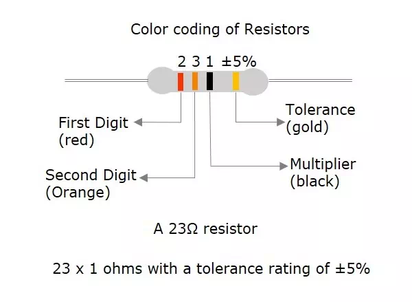
Tolerance is the range of value up to which a resistor can withstand without getting destroyed. This is an important factor. The following figure shows how the value of a resistor is determined by colour code.
The five colour band resistors are manufactured with tolerance of 2% and 1% and also for other high accuracy resistors. In these five band resistors, the first three bands represent digits, fourth one indicates multiplier and the fifth represents tolerance.
Let us look at an example to understand the colour coding process.
Example 1 − Determine the value of a resistor with a colour code yellow, blue, orange and silver.
Solution − The value of yellow is 4, blue is 6, orange is 3 which represents multiplier. Silver is ±10 which is the tolerance value.
Hence the value of the resistor is 46×103 = 46kΩ
The maximum resistance value for this resistor is
46kΩ or 46000Ω + 10% = 46000 + 4600 = 50600Ω = 50.6kΩ
The minimum resistance value for this resistor is
46kΩ or 46000Ω – 10% = 46000 – 4600 = 41400Ω = 41.4kΩ
After having gone through different details regarding resistors, we have some terms to learn. Also we have to deal with different behaviors of a resistor for few types of connections.