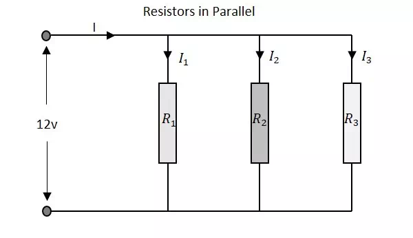
Let us observe what happens, when few resistors are connected in Parallel. Let us consider three resistors with different values, as shown in the figure below.
Resistance
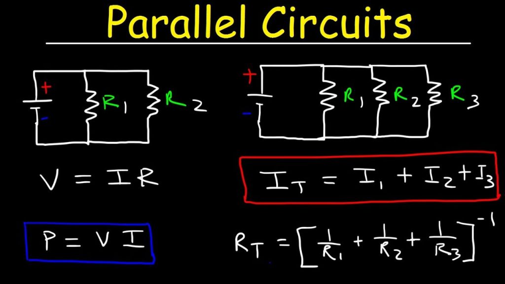
The total resistance of a circuit having Parallel resistors is calculated differently from the series resistor network method. Here, the reciprocal (1/R) value of individual resistances are added with the inverse of algebraic sum to get the total resistance value.
Total resistance value of the resistor network is −
1R=1R1+1R2+1R31R=1R1+1R2+1R3
Where R1 is the resistance of 1st resistor, R2 is the resistance of 2nd resistor and R3 is the resistance of 3rd resistor in the above resistor network.
For example, if the resistance values of previous example are considered, which means R1 = 1KΩ, R2 = 5KΩ and R3 = 9KΩ. The total resistance of parallel resistor network will be −
1R=11+15+191R=11+15+19
=45+9+545=5945=45+9+545=5945
R=4559=0.762KΩ=76.2ΩR=4559=0.762KΩ=76.2Ω
From the method we have for calculating parallel resistance, we can derive a simple equation for two-resistor parallel network. It is −
R=R1×R2R1+R2R=R1×R2R1+R2
Voltage
The total voltage that appears across a Parallel resistors network is same as the voltage drops at each individual resistance.
The Voltage that appears across the circuit −
V=V1=V2=V3V=V1=V2=V3
Where V1 is the voltage drop of 1st resistor, V2 is the voltage drop of 2ndresistor and V3 is the voltage drop of 3rd resistor in the above resistor network. Hence the voltage is same at all the points of a parallel resistor network.
Current
The total amount of current entering a Parallel resistive network is the sum of all individual currents flowing in all the Parallel branches. The resistance value of each branch determines the value of current that flows through it. The total current through the network is
I=I1+I2+I3I=I1+I2+I3
Where I1 is the current through the 1st resistor, I2 is the current through the 2nd resistor and I3 is the current through the 3rd resistor in the above resistor network. Hence the sum of individual currents in different branches obtain the total current in a parallel resistive network.
A Resistor is particularly used as a load in the output of many circuits. If at all the resistive load is not used, a resistor is placed before a load. Resistor is usually a basic component in any circuit.