That, at least, could be one reaction to this chapter. But over the years I’ve become convinced that new microcontroller programmers should understand interrupts before being introduced to any complex peripherals such as timers, UARTs, ADCs, and all the other powerful function blocks found on a modern microcontroller. Since these peripherals are commonly used with interrupts, any introduction to them that does not include interrupts is an incomplete introduction, and each peripheral would have to be revisited after the concept of interrupts was finally introduced. That just strikes me as wasteful.
So, let’s talk about interrupts. I used to be intimidated by them when I started programming μCs, and maybe you are too. That is very much the wrong attitude – interrupts are not some kind of magic, but just a very powerful and very manageable technique for dealing with all kinds of things that need attention at “unexpected” times.
Odd Memory B
Consider this scenario. We need to monitor a GPIO input and respond to that input going active within a few microseconds. Not tens of milliseconds as was the case with our human button pushes, but a few microseconds. The μC program could be at any point in its execution when this input goes active. We need to do the equivalent of monitoring this signal not a hundred times per second, but hundreds of thousands of times per second, while still doing all of the other things our program needs to do. How can we possibly respond so quickly, and still have any time to do any other work in our program? Interrupts are the answer.
NOW YOU SEE IT, NOW YOU DON’T
An interrupt is a signal (generally called an “interrupt request”) to the CPU to immediately begin executing different code, code that is written to respond to the cause of the interrupt. “Immediately” can be as soon as the end of the current instruction, in the best case. The time between the generation of the interrupt request and the entry into the ISR is called the “interrupt latency,” and faster (lower latency) is always better. The CPU will remember the location of the next instruction it was going to execute by storing that instruction address in a register or memory location, and will then jump directly to the code designated by the programmer for that particular interrupt. In addition to saving the address of the next instruction, it will often also save the CPU status register and disable further interrupts. It will also, in most cases, automatically clear the interrupt request that triggered the ISR entry, so that a single interrupt request does not result in the ISR being entered multiple times. Occasionally, depending on interrupt type and microcontroller design, it will require user code in the ISR to explicitly clear the interrupt request. It is very important to check the datasheet for a given interrupt source to see if the ISR code must clear the interrupt request, or the uC will just keep re-interrupting on the one interrupt request event forever.
A microcontroller CPU will be designed to respond to a number of different interrupt sources (perhaps 10 to 100 sources, typically), and each source can have specific user-written code which executes when that interrupt triggers. The code that executes for an interrupt is called the “interrupt service routine” or ISR. The “now you see it, now you don’t” heading refers to what you would see if you were watching the code execute in slow motion. The program counter would be moving from one instruction to the next, and then when the interrupt triggered the PC would suddenly end up in some totally different area of the program (the entry point of the ISR). Then, when the ISR was complete, the PC would just as suddenly be pointing back to the next instruction, as if nothing had happened.
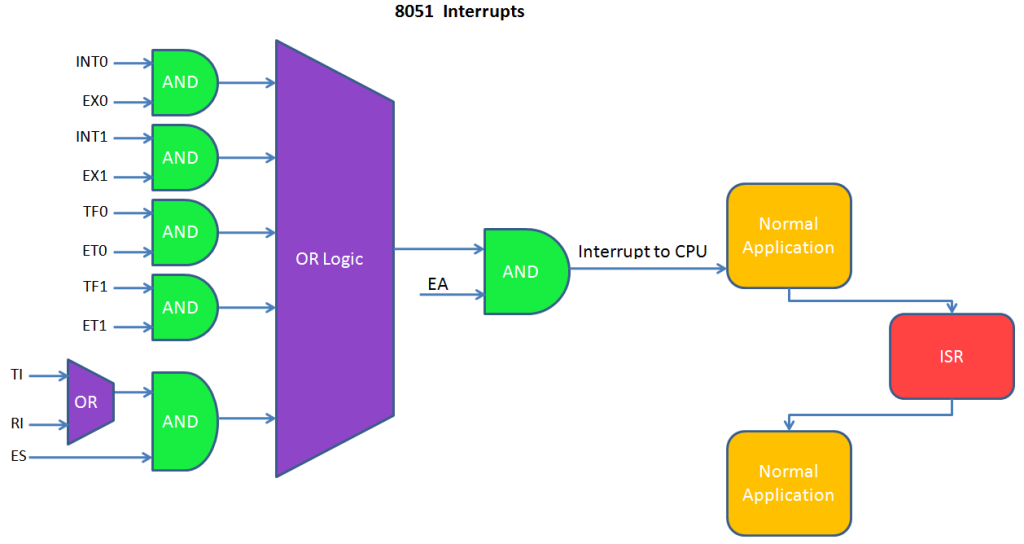
Interrupts are always off or disabled when coming out of RESET. In fact, they are doubly disabled. Each individual interrupt source is disabled, and also the global CPU interrupt flag is disabled. For an interrupt to happen (to have its ISR run), both the individual interrupt must be enabled, and the CPU global interrupts must be enabled. And finally, of course, the interrupt condition itself must occur e.g. a pin being driven low, or a timer rolling over, or whatever the particular interrupt is triggered by.
It is up to the user program to select which interrupts to enable, and at what points in the program execution to enable them (and once enabled, an interrupt can be disabled again, then re-enabled, as often as needed). The user program will also have an ISR (very similar to a function) for each interrupt that will be enabled, and each of these ISRs will be mapped to its corresponding interrupt source. It is crucial that any interrupt that is enabled, ever, has a valid ISR mapped to it. Otherwise, when the interrupt triggers, the CPU will start trying to execute code in some garbage location AKA in the weeds, and that’s the end of that. Or, if you’re lucky, the compiler will have supplied an Oops! ISR for all unused interrupts, and with your debugger you’ll find the μC looping in that ISR and figure out where you went wrong.
This diagram attempts to show how an interrupt, if enabled, pauses the background code and runs the associated ISR:


