
So, let’s test this code! If the display is wired up correctly, and all the timing delays are correct, then the display should fire right up. I don’t find them at all finicky when hardware and software are correct. So here’s a simple main() that initializes the display and exercises it. It uses sprintf to format output strings, because it’s easy. Others might prefer to use itoa.
Only main() is shown here. You’ll need to include any required files. I’d also suggest that you put your delay code in a delay.c file with associated delay.h, and your LCD code in an lcd.c file with associated lcd.h. Then you’ll include those two .h files as well into your main C file – call it LCD1_AVR.c.
int main(void)
{
char buf[LCD_WIDTH+1];
unsigned int count = 0;
lcd_init();
lcd_display(0, 0, "Hello");
lcd_display(4, 1, "World!"); // shifted over to test XY functionality
while (1)
{
sprintf(buf, "COUNT: %5u", count);
lcd_display(0, 3, buf);
count++;
ms_delay(1000); // one count per second
}
}
If you want you can blink an LED inside your loop as well, to let you know the loop is running even if your LCD doesn’t work. You can even blink the LCD backlight if you have wired it up to a GPIO pin. In any case, here is a picture of the docking board, with AVR plug-in, running the above code:
SOME DETAILS AS SEEN ON THE SCOPE
Here is a scope picture of some LCD control and data signals while writing out a string to the display, using busy flag waiting. It may help you to better understand what is happening.
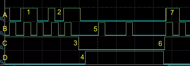
The signals are as follows:
· A: Data bit D7 (also BF)
· B: E pulse
· C: RW signal (Read = 1, Write = 0)
· D: RS signal (Date = 1, Command = 0)
The points of interest are:
- BF still high from last write (1st of the 2 E pulses for each display status read)
- BF now low at the end of 1st of 2 E pulses for next display status read), display is ready
- Switch from READ to WRITE
- Switch from CMD to DATA
- Write one data character using 2 E pulses
- Switch to READ and CMD to start checking for BF
- BF is high (busy) from the just-completed write, keep reading until it goes low
DO WE HAVE ANY POTENTIAL DATA CORRUPTION ISSUES – AVR VERSION?
Remember, we must always ask this question when, among other things, we are doing RMW on a GPIO port, as we are doing here. The answer, for the port pins we have chosen, is NO, because we are using the entire 8-bit port for the LCD, and thus there is no possibility that any ISR could be using any of the pins for other purposes. This assumes that we aren’t also calling LCD functions in an ISR – that would be a problem! If, on the other hand, we were using, say, 4 bits of one port for data, and 4 bits of another port for control, then it would be quite possible that the other 4 bits of each of the two ports might be used in an ISR, and we would have to check for that. So we did ourselves a favor by using up all the bits of one port for our LCD connections.
THE LCD SOURCE CODE – STM32 VERSION
For now I’m not going to show an STM32 version of the LCD code. The main reason is that I have a bit of a trick up my sleeve for the STM32 but it has to wait until the next chapter on timers. The other reason is that it should be a trivial effort to convert the AVR code to STM32 code. This will just involve configuring the appropriate GPIO pins and accessing them as we’ve already seen, and also figuring new delay values if not using the busy flag.
DO WE HAVE ANY POTENTIAL DATA CORRUPTION ISSUES – STM32 VERSION?
We can’t say NO as quickly in this case, since STM32 ports are 12 bits wide and we’re only using 8 bits. So it is something we would need to keep in mind if and when we assigned any of those remaining 4 port pins. If any of them were manipulated in an ISR, then we would have to protect our LCD port accesses with some form of atomic action. Remember that the STM32 has atomic set and reset registers that we can use, but when it comes to setting the 4 bits of data we can’t easily use those (we can, but it would take some additional code), so we would be reduced to turning off the offending interrupt(s) while writing the 4 data bits. The best

Comments are closed