PCI-Express (Peripheral Component Interconnect Express) or PCIe is a bus standard that replaced PCI and PCI-X. PCI-SIG (PCI Special Interest Group) creates and maintains the PCIe specification.
PCIe is used in all computer applications including enterprise servers, consumer personal computers (PC), communication systems, and industrial applications.

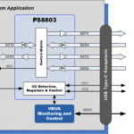
Unlike the older PCI bus topology, which uses shared parallel bus architecture, PCIe is based on point-to-point topology, with separate serial links connecting every device to the root complex (host). Additionally, a PCIe link supports full-duplex communication between two endpoints. Data can flow upstream (UP) and downstream (DP) simultaneously. Each pair of these dedicated unidirectional serial point-to-point connections is called a lane, as depicted in Fig. 1.8. The PCIe standard is constantly under improvement, with PCIe 3.0 being the latest version of the standard available in the market (Table 1.1). The standardization body is currently working on defining Gen4. Other important features of PCIe include power management, hot-swappable devices, and the ability to handle peer-to-peer data transfers (sending data between two end points without routing through the host) [14]. Additionally, PCIe simplifies board design by utilizing a serial technology, which drastically reduces the wire count when compared to parallel bus architectures.

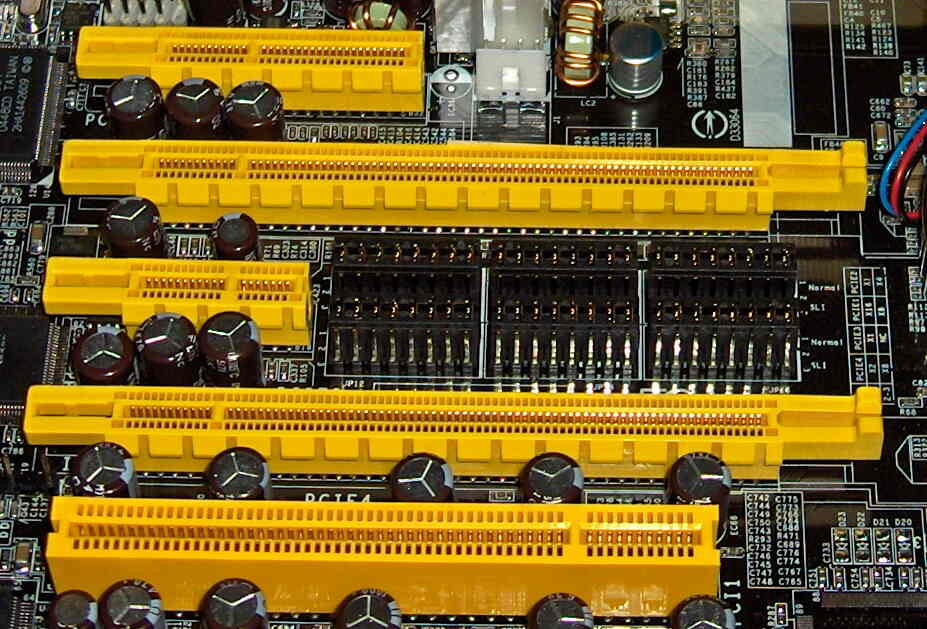
The PCIe link between two devices can consist of 1–32 lanes. The packet data is striped across lanes, and the lane count is automatically negotiated during device initialization. The PCIe standard defines slots and connectors for multiple widths: ×1, ×4, ×8, ×16, ×32. This allows PCIe to serve lower throughput, cost-sensitive applications as well as performance-critical applications. PCIe uses a packet-based layered protocol, consisting of a transaction layer, a data link layer, and a physical layer, as shown in Fig. 1.9. The transaction layer handles packetizing and de-packetizing of data and statusmessage traffic. The data link layer sequences these Transaction Layer Packets (TLPs) and ensures that they are reliably delivered between two endpoints. If a transmitter device sends a TLP to a remote receiver device and a CRC error is detected, the transmitter device gets a notification back. The transmitter device automatically replays the TLP. With error checking and automatic replay of failed packets, PCIe ensures very low Bit Error Rate (BER). The Physical Layer is split in two parts: the Logical Physical Layer and the Electrical Physical Layer. The Logical Physical Layer contains logic gates for processing packets before transmission on the Link, and processing packets from the Link to the Data Link Layer. The Electrical Physical Layer is the analog interface of the Physical Layer: it consists of differential drivers and receivers for each lane. TLP assembly is shown in Fig. 1.10. Header and Data Payload are TLP’s core information: Transaction Layer assembles this section based on the data received from the application software layer. An optional End-to-End CRC (ECRC) field can be appended to the packet. ECRC is used by the ultimate targeted device of this packet to check for CRC errors inside Header and Data Payload. At this point, the Data Link Layer appends a sequence ID and local CRC (LCRC) field in order to protect the ID. The resultant TLP is forwarded to the Physical Layer which concatenates a Start and End framing characters of 1 byte each to the packet. Finally, the packet is encoded and differentially transmitted on the Link by using the available Lanes. Today, PCIe is a high volume commodity interconnect used in virtually all computers, from consumer laptops to enterprise servers, as the primary motherboard technology that interconnects the host CPU with on-board ICs and add-on peripheral expansion cards.