We have already studied the voltage divider concept in resistors topic and we know that the voltage divider circuit is able to produce the output voltage which is a fraction of the input voltage.

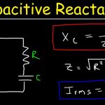
By replacing the resistor R2 with a capacitor C in the above circuit the voltage drop across the two components changes with the input frequency because reactance of the capacitor varies with the frequency.Now the output voltage across the capacitor depends on the input frequency. Using this concept we can construct passive low and high pass filters by replacing one of the resistors with a capacitor in a voltage divider circuit.
Capacitor behaviour in Low Pass Filter

For the Low pass filter the resistor R2 is replaced by the capacitor C1. At normal frequency the circuit is as shown in the above figure. When the frequency is zero the reactance value is very high which is nearly equal to infinity. At this condition circuit acts as an open circuit. When frequency is very high the reactance value reaches to zero and the circuit acts as a closed circuit. Both of these behaviour are shown in the above figure.