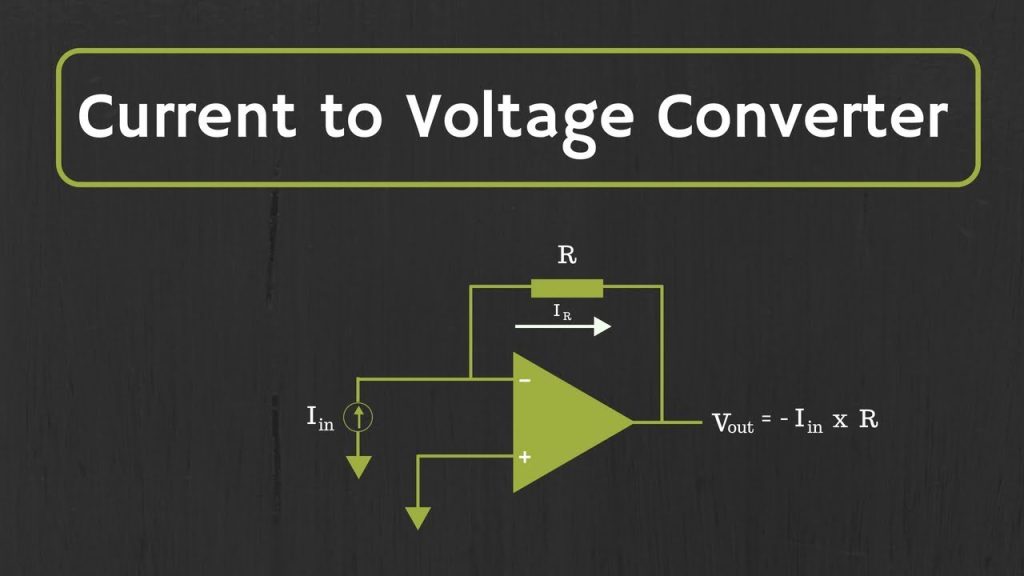
An operational amplifier current-to-voltage converter, also known as a Trans-Impedance amplifier, is a circuit which converts the change in the input current to a corresponding output voltage. The current to voltage converter circuit is most commonly used to amplify the current output of photodiodes, photo-detectors, accelerometers and other sensor devices to a noticeable and usable voltage level.
A simple current-to-voltage converter circuit will have a feedback resistor, with a large value of resistance. The gain of the amplifier is dependent on this resistor. Depending on the application, a current-to-voltage converter can be constructed in different ways. All the configurations convert the low-level current output of a sensor device to a significant voltage level. The gain and the bandwidth of the circuit changes with different types of sensors.

The circuit of a basic current-to-voltage converter is shown in the figure above. The sensor device, in this case is a photo-diode, and it is connected to the inverting input terminal and the non-inverting input terminal is grounded. This provides a low impedance load for the photo-diode, which keeps the voltage across the photo-diode low. The high gain of the op-amp keeps the photo-diode current, Ip, equal to the feedback current through resistor Rf. The input offset voltage due to the photo-diode is very low, since the photo-diode has no external bias. This provides a large output gain, without any output offset voltage.
The output voltage of the above circuit can be given as,
Vout = – IP.Rf
The above equation satisfies only for the DC and low-frequency gain current-to-voltage converter. If the gain is large, any input offset voltage at the non-inverting input of the op-amp will result in an output offset voltage. To minimize these effects, the current-to-voltage converters are usually designed with FETs at the op-amp input, which have very low input offset voltages.


Comments are closed