I-V characteristics of zener diode make it suitable for application such as a voltage regulator. A voltage stabilizer is a combination of elements that are designed to ensure the output voltage of a supply fairly remains constant. Excess voltage protection is done by using zener diodes because there will be reverse current due to minority charge carriers starts flowing through the diode after the reverse bias voltage exceeds a certain value.
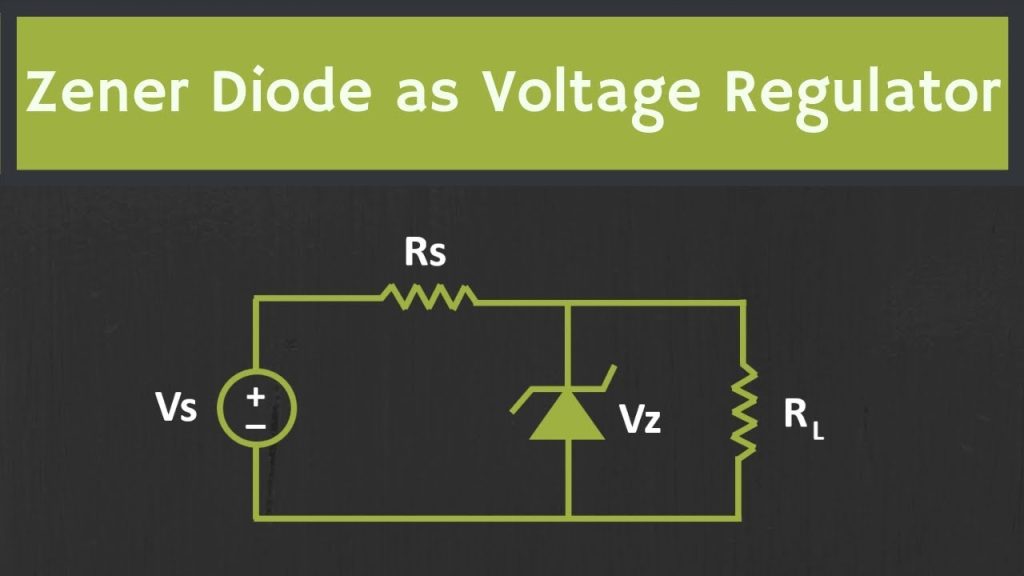
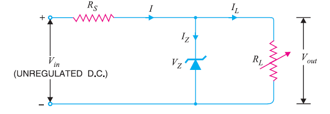
Keeping the zener diode in parallel with a variable load resistance RL, ensures a constant output voltage even though the load current and the supply voltage varies. In practical circuits the simplest form of current source is a resistor. The key in using the zener diode as voltage regulator is that as long as the zener diode is reverse biased, the flow of current greater than a few micro amperes must be accompanied by a voltage greater than the Zener voltage.
This type of arrangement of the circuit provides safety for equipment connected to terminals. This arrangement of regulator circuit is referred to as a shunt regulator in which the regulating element is placed in parallel with the load. The input voltage to the system is a few volts and as long as it is more than the desired output voltage, a stable voltage will be produced across the zener diode.
Usually the reverse current should not exceed normal value but, if due to any fault in circuit construction the current exceeds maximum allowable limit, the system will damage permanently. However to avoid unbalanced performance, zener diodes are used for voltage reference in many measuring instruments.
As the input voltage increases, current through the zener diode increases, but the drop in voltage remains constant which is the necessary feature required for zener diodes. Therefore, reverse current in the circuit has increased, voltage drop across the resistor increases by an amount equal to the difference between the applied input voltage and the zener knee voltage of the zener diode.
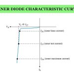
The output voltage of regulator system is fixed as the zener knee voltage of the zener diode and can be used in power devices requiring a fixed voltage of firm value. The zener diode will continue in regulating the voltage till the zener diode current falls below the minimum Iz min value in the reverse breakdown region.
When the load is not connected across the zener diode, no load current will be conducted and all the current due to the circuit will pass through the zener diode dissipating maximum amount of power that causes overheating of the diode and damages permanently.
Selecting the appropriate values of series resistance Rs is also important because it also causes greater diode current, so that maximum power dissipation of the diode should not be exceeded under no load or at high impedance condition.
Whenever a load is connected in parallel with zener diode, voltage across the load is same as the zener diode voltage. However the source voltage must be greater than the zener voltage and the upper limit of zener current depends on the power rating of the zener diode; otherwise the zener voltage will simply follow the applied input voltage.
It is also necessary that both zener diode and resistor should have a high rating of power to handle all of the current across the circuit. If a decoupling capacitor is present across the zener diode, it is more useful in providing additional smoothing to the DC supply which is necessary to stabilize the voltage.