Primary distribution systems
Primary distribution systems consist of feeders that deliver power from distribution substations to distribution transformers. A feeder usually begins with a feeder breaker at the distribution substation. Many feeders leave substation in a concrete ducts and are routed to a nearby pole.
Primary and secondary power distribution systems (layouts explained)
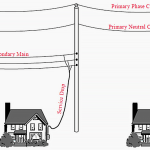
At this point, underground cable transitions to an overhead three-phase main trunk. The main trunk is routed around the feeder service territory and may be connected to other feeders through normally-open tie points. Underground main trunks are possible-even common in urban areas, but cost much more than overhead construction.
Lateral taps off of the main trunk are used to cover most of a feeder’s service territory. These taps are typically single phase, but may also be two phases or three phases.
Laterals can be directly connected to main trunks, but are more commonly protected by protective devices such as fuses, re-closers, or automatic sectionalizers.
Overhead laterals use pole-mounted distribution transformers to serve customers and underground laterals use pad mount transformers. Feeder routes must pass near every customer. To accomplish this, each substation uses multiple feeders to cover an allocated service territory.
An illustrative feeder showing different types of laterals and devices is shown in Figure 1.
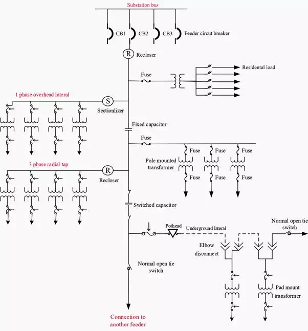
Figure 1 – A primary distribution feeder showing major components and characteristics
The simplest primary distribution system consists of independent feeders with each customer connected to a single feeder. Since there are no feeder interconnections, a fault will interrupt all downstream customers until it is repaired.
This configuration is called a radial system and is common for low-density rural areas where more complex systems are cost prohibitive.
A slightly more common configuration connects two feeders together at their endpoints with a normally open tie switch. This primary loop increases reliability by allowing customers downstream of a fault to receive power by opening an upstream switch and closing the tie switch. The only customers that cannot be restored are those in switchable section where the fault occurred.
Many distribution systems have multiple tie switches between multiple feeders. Reliability benefits are similar to a primary loop with greater switching flexibility.
These highly interconnected primary distribution systems are referred to as radially operated networks.
Certain classes of customers require higher reliability than a single feeder can provide.
Primary selective service connects each customer to a preferred feeder and an alternate feeder. If the preferred feeder becomes de-energized, a transfer switch disconnects the preferred feeder and connects the alternate feeder.
Secondary selective service achieves similar results by using switches on secondary voltages rather than primary voltages. With secondary selective service, each distribution transformer must be able to supply the entire load for maximum reliability benefits.
Spot Networks are used for customers with the highest reliability requirements. This configuration connects two or more transformers (fed from at least two feeders) in parallel to energize the secondary bus. To prevent reverse power flow through the transformers, special network protectors with sensitive reverse power relays are used. Spot networks allow multiple component failures to occur without any noticeable impact on customers.
They are common in central business districts and high-density areas and are being applied frequently in outlying areas for large commercial services where multiple supply feeders can be made available.
Some typical primary distribution system configurations are shown in Figure 2.
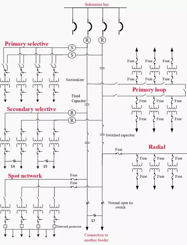
Figure 1 – Typical primary distribution system