A low-voltage network or secondary network is a part of electric power distribution which carries electric energy from distribution transformers to electricity meters of end customers.
Secondary networks are operated at a low voltage level, which is typically equal to the mains voltage of electric appliances. Most modern secondary networks are operated at AC rated voltage of 100–120 or 230–240 volts, at the frequency of 50 or 60 hertz.
Operating voltage, required number of phases (three-phase or single-phase) and required reliability dictate topology and configuration of the network.
Electric power distribution systems are designed to serve their customers with reliable and high-quality power. The most common distribution system consists of simple radial circuits (feeders) that can be overhead, underground, or a combination.
From the distribution substation, feeders carry the power to the end customers, forming the medium-voltage or primary network, operated at a medium voltage level, typically 5–35 kV. Feeders range in length from a few kilometres to several tens of kilometres. As they must supply all customers in the designated distribution area, they often curve and branch along the assigned corridors.
Distribution transformers or secondary transformers, placed along feeders, convert the voltage from the medium to a low voltage level, suitable for direct consumption by end customers (mains voltage).

Distribution transformer (photo credit: skselectricals.in)
Typically, a rural primary feeder supplies up to 50 distribution transformers, spread over a wide region but the figure significantly varies depending on configuration. They are sited on pole tops, cellars or designated small plots.
From these transformers, low voltage or secondary network branches off to the customer connections at customer premises, equipped with electricity meters.

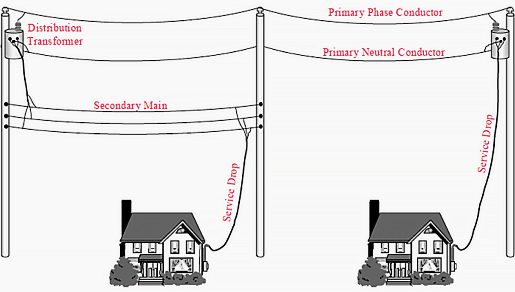
Figure 3 – Service drop to primary (right) service drops to secondary mains (left)
Customers are connected to distribution systems via service drops. Customers close to a distribution transformer are able to have service drops directly connected to transformer secondary connections. Other customers are reached by routing a secondary main for service drop connections.
These two types of service connections are shown in Figure 3 above.
Systems utilizing secondary mains are characterized by a small number of large distribution transformers rather than a large number of small distribution transformers
This can be cost effective for areas with low load density and/or large lot size, but increases ohmic losses and results in higher voltage drops. Increased line exposure tends to reduce reliability while fewer transformers tend to increase reliability.
Many underground systems connect service drops directly to distribution transformers and do not use secondary mains. This forces distribution transformers to be located within several hundred feet of each customer, but eliminates the reliability concerns associated with T-splices that are required to connect underground service drops to underground secondary mains.


