
Earthing purpose
While working as an electrical engineer, there are a dozen things you must remember, especially the ones that concern the safety. Whether you are in the electrical design field or in execution, you must admit that earthing is one of the fundamentals that you must never forget. Let’s talk about earthing.
Earthing facts
Generally, earthing is always some reference for various concepts in electrical engineering and that’s very interesting. This technical article will put all the earthing facts on the table in order to remind all of us engineers. So, let’s start.
Earthing systems have the following general purpose: Protection of life and property in the events of 50-Hz-faults (short circuits and earth faults) and transient phenomena (lightning, switching operations).
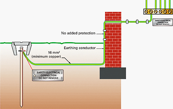
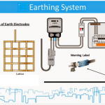
The general layout of a complete earthing system with sections for low voltage, high voltage and buildings and building services is shown in Figure 1. The most important definitions related to earthing are grouped below.
Earth is the term for the earth as a location and for the earth as material, e.g. the soil types of humus, clay, sand, gravel, rock. Reference earth (neutral earth) is that part of the earth, particularly the surface outside the area of influence of an earth electrode or an earthing system, in which there are no detectable voltages resulting from the earthing current between any two random points.
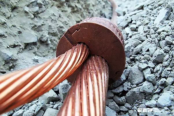
Earth electrode is a conductor embedded in the ground and electrically connected to it, or a conductor embedded in concrete that is in contact with the earth over a large area (e.g. foundation earth).
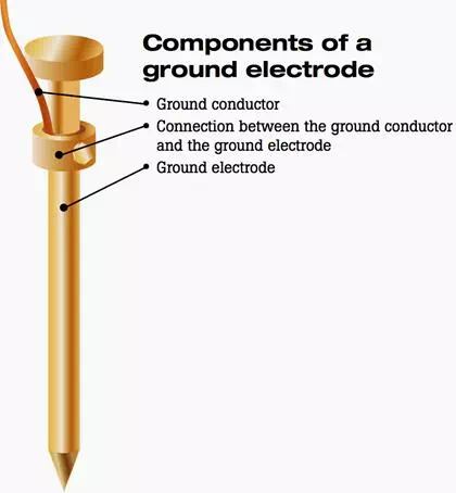
Components of a ground electrode
Earthing conductor is a conductor connecting a system part to be earthed to an earth electrode, so long as it is laid out of contact with the ground or is insulated in the ground.
If the connection between a neutral or phase conductor and the earth electrode includes an isolating link, a disconnector switch or an earth-fault coil, only the connection between the earth electrode and the earth-side terminal of the nearest of the above devices is deemed to be an earthing conductor.
Main earthing conductor is an earthing conductor to which a number of earthing conductors are connected.
It does not include:
Earthing conductors joining the earthed parts of the single units of three-phase assemblies (3 instrument transformers, 3 potheads, 3 post insulators etc.),
With compartment-type installations: earthing conductors that connect the earthed parts of several devices of a compartment and are connected to a (continuous) main earthing conductor within this compartment.
Earthing conductor connection
Earthing system is a locally limited assembly of conductively interconnected earth electrodes or metal parts operating in the same way (e.g. tower feet, armouring, metal cable sheaths) and earthing conductors.
To earth means to connect an electrically conductive part to the ground via an earthing system. Earthing is the total of all measures used for earthing.
Specific earth resistivity ρE is the specific electrical resistivity of the ground. It is generally stated in Ω m2/m = Ω m and indicates the resistance between two opposite cube faces of a cube of soil with sides of 1 m.
Figure 1 – Earthing system with equipotential bonding between HV/LV indoor switchgear and building/building services
Dissipation resistance RA of an earth electrode is the resistance of the earth between the earth electrode and the reference earth. RA is in practice a real resistance.
Earthing impedance ZE is the AC impedance between an earthing system and the reference earth at operating frequency. The value of the earthing impedance is derived from parallelling the dissipation resistances of the earth electrodes and the impedances of connected conductor strings, e.g. the overhead earth wire and cables acting as earth electrodes.
Impulse earthing resistance Rst is the resistance presented to the passage of lightning currents between a point of an earthing system and the reference earth.
Protective earthing is the earthing of a conductive component that is not part of the main circuit for the protection of persons against unacceptable touch voltages.
System earthing is the earthing of a point of the main circuit necessary for proper operation of devices or installations. It is termed:
Direct, if it includes no resistances other than the earthing impedance.
Indirect, if it is established via additional resistive, inductive or capacitive resistances.
Lightning protection earthing is the earthing of a conductive component that is not part of the main circuit to avoid flashovers to the operational live conductors resulting from lightning as much as possible (back flashovers).
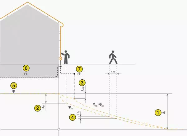
Electrical potential on the earth surface and voltages as current passes through the foundation earth electrode (FE) and control earth electrode (CE)
Where:
UE – Earthing voltage
UB1 – Touch voltage without potential control (on foundation earth electrode)
UB2 – Touch voltage with potential control (foundation earth electrode and control earth electrode)
US – Step voltage (without control earth electrode)
φ – Earth surface potential
FE – Foundation earth electrode
CE – Control earth electrode (ring earth electrode)
Earthing voltage UE is the voltage occurring between an earthing system and the reference earth.
Earth surface potential φ is the voltage between a point on the surface of the earth and the reference earth.
Touch voltage UB is the part of the earthing voltage that can be shunted through the human body, the current path being through the human body from hand to foot (horizontal distance from exposed part about 1 m) or from hand to hand.
If there is a lightning stroke, the lightning current is routed through the down-conductors into the earthing system and the earth. The resistance of the down-conductor and the earth causes a voltage drop, which can lead to so-called touch voltage.
The touch voltage is the voltage between a component (e.g. the down-conductor) and earth potential. The current flows from the hand to the foot through the body. The potential hazard must be reduced by technical measures, e.g. a control earth electrode.
Step voltage US is that part of the earthing voltage that can be shunted by a person with a stride of 1 m, with the current path being through the human body from foot to foot.
Potential control consists in influencing the earth potential, particularly the earth surface potential, by earth electrodes to reduce the step and touch voltage in the outer area of the earthing system.
Earth fault is an electrical connection between a conductor of the main circuit with earth or an earthed part caused by a defect. The electrical connection can also be caused by an arc.
Earth fault current IF is the current passing to earth or earthed parts when an earth fault exists at only one point at the site of the fault (earth fault location). This is:
The capacitive earth-fault current IC in networks with isolated neutral
The earth-fault residual current IRest in networks with earth-fault compensation
The zero-sequence current I”k1in networks with low-resistance neutral earthing.
Also includes networks with isolated neutral point or earth-fault compensators in which the neutral point is briefly earthed at the start of the fault.
Earthing current IE is the total current flowing to earth via the earthing impedance. The earthing current is the component of the earth-fault current IF which causes the rise in potential of an earthing system.