Classification by location:
The following examples are distinguished:
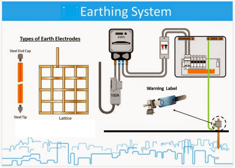
1. Surface earth electrodes are earth electrodes that are generally positioned at shallow depths to about 1 m. They can be of strip, bar or stranded wire and be laid out as radial, ring or meshed earth electrodes or as a combination of these.
2. Deep earth electrodes are earth electrodes that are generally positioned vertically at greater depths. They can be of tubular, round or sectional material.
Classification by shape and cross section:
The following examples are distinguished: Strip, stranded wire and tube earth electrodes.
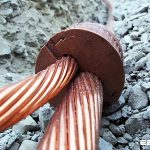
Natural earth electrodes are metal parts in contact with the ground or water, directly or via concrete, whose original purpose is not earthing but they act as an earth electrode. They include pipes, caisson walls, concrete pile reinforcement, steel parts of buildings etc.
Cables with earthing effect are cables whose metal sheathing, shield or armouring provides a leakage to earth similar to that of strip earth electrodes.
Foundation earths are conductors embedded in concrete that is in contact with the ground over a large area . Foundation earths may be treated as if the conductor were laid in the surrounding soil.
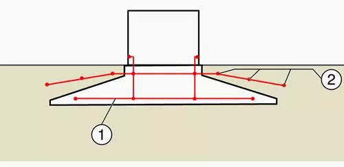 F
F
oundation and ring earth electrodes of a wind power plant
Where:
1. Foundation earth electrode
2. Ring earth electrode
Control earth electrodes are earth electrodes that by their shape and arrangement are more for potential control than for retaining a specific dissipation resistance.
Rod earth electrodes of any significant length generally pass through soil horizons of varying conductivity. They are particularly useful where more conductive lower soil horizons are available and the rod earth electrodes can penetrate these horizons sufficiently (approximately 3 m).
To determine whether more conductive lower soil horizons are available, the specific resistance of the soil at the site is measured.
The specific resistivity ρE of the soil is important for calculating earthing systems. For this reason, ρE should be measured before beginning construction work for a switchgear installation; the measurements are made using the “Wenner Method”. Measuring the step and touch voltages after setup of a switchgear installation is one way to confirm the safety of the system.
The measurements are conducted in accordance with the current and voltage method in EN 61936-1 and DIN VDE 0101. The current and voltage method also allows the earthing impedance (dissipation resistance) of the installation to be calculated by measuring the potential gradient.
Use of earth testers (e.g. Megger, Fluke or similar) to measure dissipation resistance should be restricted to single earth electrodes or earthing systems of small extent (e.g. rod earth electrode, strip earth electrode, tower earth electrode, earthing for small switchgear installations).