When the site to be protected consists of several buildings or extends beyond the range of a single capture device (lightning conductor), a protection plan must be drawn up for the area, juxtaposing the different theoretical capture surface areas.
It is always difficult to achieve total coverage of a site when it is made up of structures of different heights.
Superimposing the protection plan over the layout of the area makes it possible to see areas that are not covered, but above all it must assist in-depth consideration taking account of:
1. The probability of lightning strikes by determining the main strike points (towers, chimneys, antennae, lamp posts, masts, etc.)
2. The sensitivity of the equipment housed in the buildings (communication and computer equipment, PLCs, etc.)
3. The potential risk linked to the business or the types of material stored (fire, explosion, etc.)
It must also be remembered that the numerous links between the buildings (computer networks, remote monitoring, communications, alarms and power) can create interference as a result of the effect of the lightning’s electromagnetic field or that of the voltage gradient generated in the ground.
There are two ways in which these links can be protected:
WAY 1 – Shielding or use of Faraday cages which will, as well as protecting against these fields, primarily maintain the equipotentiality of the link (adjacent earthing conductor, twisting, conductor screen, etc.)
WAY 2 – Galvanic decoupling, which will separate buildings electrically (optocouplers, fibre optics, isolation transformers, etc).
The protection plan must take the buildings and structures to be protected against direct lightning strikes into consideration, but it must also take into account elements or non-built areas for which lightning strikes may cause destructive effects.
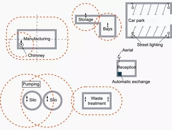 Figure 8 – Example of a protection plan
On this (imaginary) site we can see that the sensitive areas:
manufacturing, storage, processing etc., have been protected effectively by lightning conductors or by a meshed cage, but that two areas are not protected, as they are considered to be low-risk: reception area and car park.
Further consideration shows that the lamp posts lighting the car park could be struck by lightning and transmit the lightning strike to the installation, and that the reception area which houses the telephone switchboard and the paging aerial (beep) represents an area which is both vulnerable and sensitive.
The pumping station is theoretically protected by the silo lightning conductors which are much higher. A situation which must not however allow us to forget that in this case a sideways lightning strike is possible.
Down-conductors
These provide the link between the lightning conductor itself (rod, cage, wire) and the earthing electrode. They are subjected to intense currentsand must therefore be of an adequate cross-section (min. 50 mm2copper), flat (HF current), firmly fixed and follow the shortest possible route.
They must have no rises or sharp angles. The conductors can be fitted with lightning strike counters.
It is advisable to increase the number of downconductorsin order to reduce the currents in each one and the associated thermal, electrodynamic and inductive effects. Downconductors must end in a meshed, equipotential earth circuit.
The consequences in the installation of the effects caused by circulation of the lightning current in the downconductors can be minimized by:
· Increasing the number of downconductors in order to divide the current and limit the effects caused.
· Ensuring that the downconductors are interconnected with the bonding systems on all floors in the building.
· Creating equipotential bonding systems incorporating all conductive elements, including those that are inaccessible:
i. fluid pipes,
ii. protection circuits,
iii. reinforcements in concrete,
iv. metal frames, etc.
· Avoiding placing downconductors near sensitive areas or equipment (computing, telecommunications, etc.).
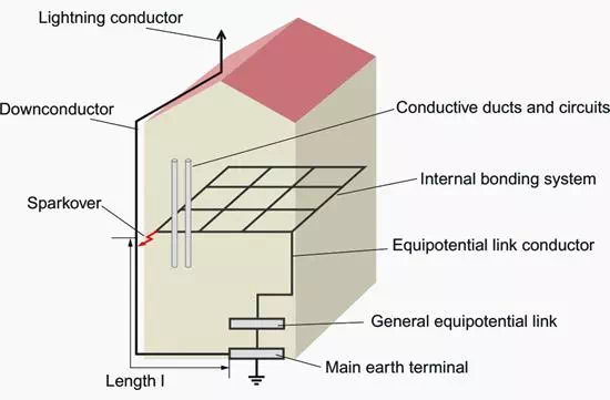 Figure 9 – Interconnection of downconductors with the bonding systems in buildings
In buildings with several floors, it is recommended that the lightning conductor downconductor(s) are connected to the bonding systems on each floor.
If this is not done, the voltage difference that occurs between the downconductors and the internal exposed conductive parts could cause a sparkover through the walls of the building.
The circulation of the HF lightning current may in fact cause a significant voltage rise in the downconductor (several hundred kV) due to the increase in its high frequency impedance.
Earthing system
This is an essential element in protection against lightning: all the exposed conductive parts, which are themselves interconnected, must be connected, and the system must be capable of discharging the lightning current, avoiding a voltage rise in the earthing system itself and the surrounding ground.
Although it must be low enough (< 10 Ω), the low frequency resistance value of the earthing electrode is less important than its shape and size as far as the discharge of the high frequency lightning current is concerned.
As a general rule, each downconductor must end in an earthing electrode which can consist of conductors (at least three) in a crow’s foot layout buried at least 0.5 m deep, or earth rods, preferably in a triangular layout.
In addition, IEC 62305 implies that the lightning conductor downconductors should be interconnected with the bonding system with the main equipotential link.
When possible, it is always advisable to increase the number of downconductors and linking points (each floor), and thus to increase the overall scale of the equipotential bonding system. At the same time as this, the earthing system must of course be capable of discharging the lightning currents in order to limit the voltage rise of the bonding system as much as possible.
There must only be one earthing system.
Separate, independent circuits (power, computers, electronic, communications) should be prohibited, but this does not exclude multiple earthing electrodes (electrodes) if they are all interconnected.