When a voltage source is applied to an RC circuit, the capacitor, C charges up through the resistance, R
All Electrical or Electronic circuits or systems suffer from some form of “time-delay” between its input and output, when a signal or voltage, either continuous, ( DC ) or alternating ( AC ) is firstly applied to it.
This delay is generally known as the time delay or Time Constant of the circuit and it is the time response of the circuit when a step voltage or signal is firstly applied. The resultant time constant of any electronic circuit or system will mainly depend upon the reactive components either capacitive or inductive connected to it and is a measurement of the response time with units of, Tau – τ
When an increasing DC voltage is applied to a discharged Capacitor, the capacitor draws a charging current and “charges up”, and when the voltage is reduced, the capacitor discharges in the opposite direction. Because capacitors are able to store electrical energy they act like small batteries and can store or release the energy as required.
The charge on the plates of the capacitor is given as: Q = CV. This charging (storage) and discharging (release) of a capacitors energy is never instant but takes a certain amount of time to occur with the time taken for the capacitor to charge or discharge to within a certain percentage of its maximum supply value being known as its Time Constant ( τ ).
If a resistor is connected in series with the capacitor forming an RC circuit, the capacitor will charge up gradually through the resistor until the voltage across the capacitor reaches that of the supply voltage. The time also called the transient response, required for the capacitor to fully charge is equivalent to about 5 time constants or 5T.
This transient response time T, is measured in terms of τ = R x C, in seconds, where R is the value of the resistor in ohms and C is the value of the capacitor in Farads. This then forms the basis of an RC charging circuit were 5T can also be thought of as “5 x RC”.
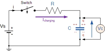
RC Charging Circuit
The figure below shows a capacitor, ( C ) in series with a resistor, ( R ) forming a RC Charging Circuit connected across a DC battery supply ( Vs ) via a mechanical switch. When the switch is closed, the capacitor will gradually charge up through the resistor until the voltage across it reaches the supply voltage of the battery. The manner in which the capacitor charges up is also shown below.
RC Charging Circuit
Let us assume above, that the capacitor, C is fully “discharged” and the switch (S) is fully open. These are the initial conditions of the circuit, then t = 0, i = 0 and q = 0. When the switch is closed the time begins at t = 0 and current begins to flow into the capacitor via the resistor.
Since the initial voltage across the capacitor is zero, ( Vc = 0 ) the capacitor appears to be a short circuit to the external circuit and the maximum current flows through the circuit restricted only by the resistor R. Then by using Kirchhoff’s voltage law (KVL), the voltage drops around the circuit are given as:

The current now flowing around the circuit is called the Charging Current and is found by using Ohms law as: i = Vs/R.
RC Charging Circuit Curves
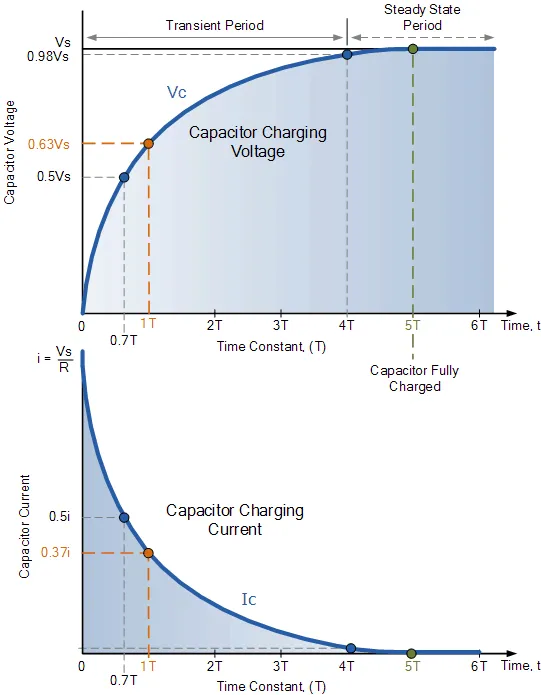
The capacitor now starts to charge up as shown, with the rise in the RC charging curve steeper at the beginning because the charging rate is fastest at the start and then tapers off as the capacitor takes on additional charge at a slower rate.
As the capacitor charges up, the potential difference across its plates slowly increases with the actual time taken for the charge on the capacitor to reach 63%of its maximum possible voltage, in our curve 0.63Vs being known as one Time Constant, ( T ).
This 0.63Vs voltage point is given the abbreviation of 1T, (one time constant).
The capacitor continues charging up and the voltage difference between Vs and Vcreduces, so to does the circuit current, i. Then at its final condition greater than five time constants ( 5T ) when the capacitor is said to be fully charged, t = ∞, i = 0, q = Q = CV. Then at infinity the current diminishes to zero, the capacitor acts like an open circuit condition therefore, the voltage drop is entirely across the capacitor.
So mathematically we can say that the time required for a capacitor to charge up to one time constant, ( 1T ) is given as:
RC Time Constant, Tau

This RC time constant only specifies a rate of charge where, R is in Ω and C in Farads.
Since voltage V is related to charge on a capacitor given by the equation, Vc = Q/C, the voltage across the value of the voltage across the capacitor ( Vc ) at any instant in time during the charging period is given as:

· Where:
· Vc is the voltage across the capacitor
· Vs is the supply voltage
· t is the elapsed time since the application of the supply voltage
· RC is the time constant of the RC charging circuit
After a period equivalent to 4 time constants, ( 4T ) the capacitor in this RC charging circuit is virtually fully charged and the voltage across the capacitor is now approx 98% of its maximum value, 0.98Vs. The time period taken for the capacitor to reach this 4T point is known as the Transient Period.
After a time of 5T the capacitor is now fully charged and the voltage across the capacitor, ( Vc ) is equal to the supply voltage, ( Vs ). As the capacitor is fully charged no more current flows in the circuit. The time period after this 5T point is known as the Steady State Period.
Then we can show in the following table the percentage voltage and current values for the capacitor in a RC charging circuit for a given time constant.
RC Charging Table
| Time Constant | RC Value | Percentage of Maximum | |
| Voltage | Current | ||
| 0.5 time constant | 0.5T = 0.5RC | 39.3% | 60.7% |
| 0.7 time constant | 0.7T = 0.7RC | 50.3% | 49.7% |
| 1.0 time constant | 1T = 1RC | 63.2% | 36.8% |
| 2.0 time constants | 2T = 2RC | 86.5% | 13.5% |
| 3.0 time constants | 3T = 3RC | 95.0% | 5.0% |
| 4.0 time constants | 4T = 4RC | 98.2% | 1.8% |
| 5.0 time constants | 5T = 5RC | 99.3% | 0.7% |
Note that as the charging curve for a RC charging circuit is exponential, the capacitor in reality never becomes 100% fully charged due to the energy stored in the capacitor. So for all practical purposes, after five time constants a capacitor is considered to be fully charged.
As the voltage across the capacitor Vc changes with time, and is a different value at each time constant up to 5T, we can calculate this value of capacitor voltage, Vc at any given point, for example.
RC Charging Circuit Example No1
Calculate the RC time constant, τ of the following circuit.
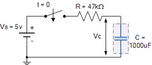
The time constant, τ is found using the formula T = R x C in seconds.
Therefore the time constant τ is given as: T = R x C = 47k x 1000uF = 47 Secs
a) What value will be the voltage across the capacitor at 0.7 time constants?
At 0.7 time constants ( 0.7T ) Vc = 0.5Vs. Therefore, Vc = 0.5 x 5V = 2.5V
b) What value will be the voltage across the capacitor at 1 time constant?
At 1 time constant ( 1T ) Vc = 0.63Vs. Therefore, Vc = 0.63 x 5V = 3.15V
c) How long will it take to “fully charge” the capacitor?
The capacitor will be fully charged at 5 time constants.
1 time constant ( 1T ) = 47 seconds, (from above). Therefore, 5T = 5 x 47 = 235 secs
d) The voltage across the Capacitor after 100 seconds?
The voltage formula is given as Vc = V(1 – e(-t/RC)) so this becomes: Vc = 5(1 – e(-100/47))
Where: V = 5 volts, t = 100 seconds, and RC = 47 seconds from above.
Therefore, Vc = 5(1 – e(-100/47)) = 5(1 – e-2.1277) = 5(1 – 0.1191) = 4.4 volts
We have seen that the charge on a capacitor is given by the expression: Q = CVand that when a voltage is firstly applied to the plates of the capacitor it charges up at a rate determined by its time constant, τ.