Oscillators are electronic circuits that generate a continuous periodic waveform at a precise frequency
Oscillators convert a DC input (the supply voltage) into an AC output (the waveform), which can have a wide range of different wave shapes and frequencies that can be either complicated in nature or simple sine waves depending upon the application.
Oscillators are also used in many pieces of test equipment producing either sinusoidal sine waves, square, sawtooth or triangular shaped waveforms or just a train of pulses of a variable or constant width. LC Oscillators are commonly used in radio-frequency circuits because of their good phase noise characteristics and their ease of implementation.
An Oscillator is basically an Amplifier with “Positive Feedback”, or regenerative feedback (in-phase) and one of the many problems in electronic circuit design is stopping amplifiers from oscillating while trying to get oscillators to oscillate.
Oscillators work because they overcome the losses of their feedback resonator circuit either in the form of a capacitor, inductor or both in the same circuit by applying DC energy at the required frequency into this resonator circuit. In other words, an oscillator is a an amplifier which uses positive feedback that generates an output frequency without the use of an input signal.
Thus Oscillators are self sustaining circuits generating an periodic output waveform at a precise frequency and for any electronic circuit to operate as an oscillator, it must have the following three characteristics.
· Some form of Amplification
· Positive Feedback (regeneration)
· A Frequency determine feedback network
An oscillator has a small signal feedback amplifier with an open-loop gain equal too or slightly greater than one for oscillations to start but to continue oscillations the average loop gain must return to unity. In addition to these reactive components, an amplifying device such as an Operational Amplifier or Bipolar Transistor is required.
Unlike an amplifier there is no external AC input required to cause the Oscillator to work as the DC supply energy is converted by the oscillator into AC energy at the required frequency.
Basic Oscillator Feedback Circuit

Where: β is a feedback fraction.
Oscillator Gain Without Feedback

Oscillator Gain With Feedback

Oscillators are circuits that generate a continuous voltage output waveform at a required frequency with the values of the inductors, capacitors or resistors forming a frequency selective LC resonant tank circuit and feedback network. This feedback network is an attenuation network which has a gain of less than one ( β <1 ) and starts oscillations when Aβ >1 which returns to unity ( Aβ =1 ) once oscillations commence.
The LC oscillators frequency is controlled using a tuned or resonant inductive/capacitive (LC) circuit with the resulting output frequency being known as the Oscillation Frequency. By making the oscillators feedback a reactive network the phase angle of the feedback will vary as a function of frequency and this is called Phase-shift.
There are basically types of Oscillators
· 1. Sinusoidal Oscillators – these are known as Harmonic Oscillators and are generally a “LC Tuned-feedback” or “RC tuned-feedback” type Oscillator that generates a purely sinusoidal waveform which is of constant amplitude and frequency.
· 2. Non-Sinusoidal Oscillators – these are known as Relaxation Oscillators and generate complex non-sinusoidal waveforms that changes very quickly from one condition of stability to another such as “Square-wave”, “Triangular-wave” or “Sawtoothed-wave” type waveforms.
Oscillator Resonance
When a constant voltage but of varying frequency is applied to a circuit consisting of an inductor, capacitor and resistor the reactance of both the Capacitor/Resistor and Inductor/Resistor circuits is to change both the amplitude and the phase of the output signal as compared to the input signal due to the reactance of the components used.
At high frequencies the reactance of a capacitor is very low acting as a short circuit while the reactance of the inductor is high acting as an open circuit. At low frequencies the reverse is true, the reactance of the capacitor acts as an open circuit and the reactance of the inductor acts as a short circuit.
Between these two extremes the combination of the inductor and capacitor produces a “Tuned” or “Resonant” circuit that has a Resonant Frequency, ( ƒr ) in which the capacitive and inductive reactance’s are equal and cancel out each other, leaving only the resistance of the circuit to oppose the flow of current. This means that there is no phase shift as the current is in phase with the voltage. Consider the circuit below.
Basic LC Oscillator Tank Circuit

The circuit consists of an inductive coil, L and a capacitor, C. The capacitor stores energy in the form of an electrostatic field and which produces a potential (static voltage) across its plates, while the inductive coil stores its energy in the form of an electromagnetic field. The capacitor is charged up to the DC supply voltage, V by putting the switch in position A. When the capacitor is fully charged the switch changes to position B.
The charged capacitor is now connected in parallel across the inductive coil so the capacitor begins to discharge itself through the coil. The voltage across C starts falling as the current through the coil begins to rise.
This rising current sets up an electromagnetic field around the coil which resists this flow of current. When the capacitor, C is completely discharged the energy that was originally stored in the capacitor, C as an electrostatic field is now stored in the inductive coil, L as an electromagnetic field around the coils windings.
As there is now no external voltage in the circuit to maintain the current within the coil, it starts to fall as the electromagnetic field begins to collapse. A back emf is induced in the coil (e = -Ldi/dt) keeping the current flowing in the original direction.
This current charges up capacitor, C with the opposite polarity to its original charge. C continues to charge up until the current reduces to zero and the electromagnetic field of the coil has collapsed completely.
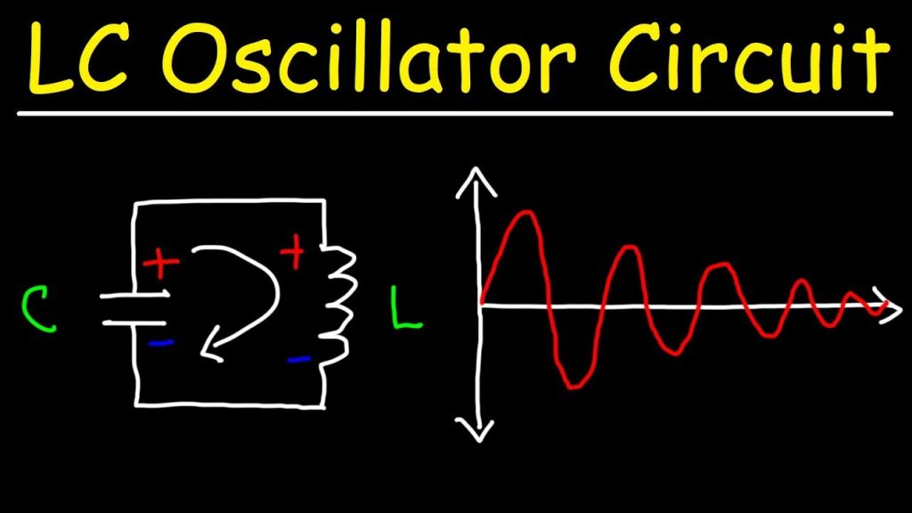
The energy originally introduced into the circuit through the switch, has been returned to the capacitor which again has an electrostatic voltage potential across it, although it is now of the opposite polarity. The capacitor now starts to discharge again back through the coil and the whole process is repeated. The polarity of the voltage changes as the energy is passed back and forth between the capacitor and inductor producing an AC type sinusoidal voltage and current waveform.
This process then forms the basis of an LC oscillators tank circuit and theoretically this cycling back and forth will continue indefinitely. However, things are not perfect and every time energy is transferred from the capacitor, C to inductor, Land back from L to C some energy losses occur which decay the oscillations to zero over time.
This oscillatory action of passing energy back and forth between the capacitor, C to the inductor, L would continue indefinitely if it was not for energy losses within the circuit. Electrical energy is lost in the DC or real resistance of the inductors coil, in the dielectric of the capacitor, and in radiation from the circuit so the oscillation steadily decreases until they die away completely and the process stops.
Then in a practical LC circuit the amplitude of the oscillatory voltage decreases at each half cycle of oscillation and will eventually die away to zero. The oscillations are then said to be “damped” with the amount of damping being determined by the quality or Q-factor of the circuit.
Damped Oscillations

The frequency of the oscillatory voltage depends upon the value of the inductance and capacitance in the LC tank circuit. We now know that for resonance to occur in the tank circuit, there must be a frequency point were the value of XC, the capacitive reactance is the same as the value of XL, the inductive reactance ( XL = XC ) and which will therefore cancel out each other out leaving only the DC resistance in the circuit to oppose the flow of current.
If we now place the curve for inductive reactance of the inductor on top of the curve for capacitive reactance of the capacitor so that both curves are on the same frequency axes, the point of intersection will give us the resonance frequency point, ( ƒr or ωr ) as shown below.
Resonance Frequency

Where: ƒr is in Hertz, L is in Henries and C is in Farads.
Then the frequency at which this will happen is given as:

Then by simplifying the above equation we get the final equation for Resonant Frequency, ƒr in a tuned LC circuit as:
Resonant Frequency of a LC Oscillator

· Where:
· L is the Inductance in Henries
· C is the Capacitance in Farads
· ƒr is the Output Frequency in Hertz
This equation shows that if either L or C are decreased, the frequency increases. This output frequency is commonly given the abbreviation of ( ƒr ) to identify it as the “resonant frequency”.
To keep the oscillations going in an LC tank circuit, we have to replace all the energy lost in each oscillation and also maintain the amplitude of these oscillations at a constant level. The amount of energy replaced must therefore be equal to the energy lost during each cycle.
If the energy replaced is too large the amplitude would increase until clipping of the supply rails occurs. Alternatively, if the amount of energy replaced is too small the amplitude would eventually decrease to zero over time and the oscillations would stop.
The simplest way of replacing this lost energy is to take part of the output from the LC tank circuit, amplify it and then feed it back into the LC circuit again. This process can be achieved using a voltage amplifier using an op-amp, FET or bipolar transistor as its active device. However, if the loop gain of the feedback amplifier is too small, the desired oscillation decays to zero and if it is too large, the waveform becomes distorted.
To produce a constant oscillation, the level of the energy fed back to the LCnetwork must be accurately controlled. Then there must be some form of automatic amplitude or gain control when the amplitude tries to vary from a reference voltage either up or down.
To maintain a stable oscillation the overall gain of the circuit must be equal to one or unity. Any less and the oscillations will not start or die away to zero, any more the oscillations will occur but the amplitude will become clipped by the supply rails causing distortion. Consider the circuit below.
Basic Transistor LC Oscillator Circuit

A Bipolar Transistor is used as the LC oscillators amplifier with the tuned LC tank circuit acts as the collector load. Another coil L2 is connected between the base and the emitter of the transistor whose electromagnetic field is “mutually” coupled with that of coil L.
“Mutual inductance” exists between the two circuits and the changing current flowing in one coil circuit induces, by electromagnetic induction, a potential voltage in the other (transformer effect) so as the oscillations occur in the tuned circuit, electromagnetic energy is transferred from coil L to coil L2 and a voltage of the same frequency as that in the tuned circuit is applied between the base and emitter of the transistor. In this way the necessary automatic feedback voltage is applied to the amplifying transistor.
The amount of feedback can be increased or decreased by altering the coupling between the two coils L and L2. When the circuit is oscillating its impedance is resistive and the collector and base voltages are 180o out of phase. In order to maintain oscillations (called frequency stability) the voltage applied to the tuned circuit must be “in-phase” with the oscillations occurring in the tuned circuit.
Therefore, we must introduce an additional 180o phase shift into the feedback path between the collector and the base. This is achieved by winding the coil of L2 in the correct direction relative to coil L giving us the correct amplitude and phase relationships for the Oscillators circuit or by connecting a phase shift network between the output and input of the amplifier.
The LC Oscillator is therefore a “Sinusoidal Oscillator” or a “Harmonic Oscillator” as it is more commonly called. LC oscillators can generate high frequency sine waves for use in radio frequency (RF) type applications with the transistor amplifier being of a Bipolar Transistor or FET.
Harmonic Oscillators come in many different forms because there are many different ways to construct an LC filter network and amplifier with the most common being the Hartley LC Oscillator, Colpitts LC Oscillator, Armstrong Oscillator and Clapp Oscillator to name a few.
LC Oscillator Example No1
An inductance of 200mH and a capacitor of 10pF are connected together in parallel to create an LC oscillator tank circuit. Calculate the frequency of oscillation.

Then we can see from the above example that by decreasing the value of either the capacitance, C or the inductance, L will have the effect of increasing the frequency of oscillation of the LC tank circuit.
LC Oscillators Summary
The basic conditions required for an LC oscillator resonant tank circuit are given as follows.
· For oscillations to exist an oscillator circuit MUST contain a reactive (frequency-dependant) component either an “Inductor”, (L) or a “Capacitor”, (C) as well as a DC power source.
· In a simple inductor-capacitor, LC circuit, oscillations become damped over time due to component and circuit losses.
· Voltage amplification is required to overcome these circuit losses and provide positive gain.
· The overall gain of the amplifier must be greater than one, unity.
· Oscillations can be maintained by feeding back some of the output voltage to the tuned circuit that is of the correct amplitude and in-phase, (0o).
· Oscillations can only occur when the feedback is “Positive” (self-regeneration).
· The overall phase shift of the circuit must be zero or 360o so that the output signal from the feedback network will be “in-phase” with the input signal.


