Passive devices are the main building blocks of electronic circuits and without them these circuits would either not work at all or become unstable.
So what are Passive Devices. Passive devices or components do not generate energy, but can store it or dissipate it. Passive devices are the main components used in electronics such as resistors, inductors, capacitors and transformers which together are required to build any electrical or electronic circuit.
As their name suggests, Passive components are electrical components that do not require any form of electrical power to operate, unlike “active devices” such as transistors, operational amplifiers and integrated circuits that require to be powered in some way to make them work.
Being passive, passive devices do not provide gain, amplification or directionality to a circuit but instead provide attenuation as they always have a gain less than one, unity. Therefore passive devices can not generate, oscillate or amplify an electrical signal.
Passive devices can be used individually or connected together within a circuit, either in a series or in a parallel combination to control complex circuits or signals, produce a phase shift to the signal or to provide some form of feedback but they can not multiply a signal by more than one because they have no power gain.
In fact passive devices consume power within an electrical or electronic circuit as they act like attenuators unlike active elements that generate or provide power to a circuit.
The component values of passive devices such as resistance in Ohms or capacitance in Farads are always positive in value (ie, >0) and never negative although some components may have a negative coefficient.
Passive devices are bi-directional components, that is they can be connected either way around within a circuit unless they have a specific polarity marking such as electrolytic capacitors. The polarity of the voltage across them is determined by conventional current flow from the positive to the negative terminal.
In both electrical circuit theory and circuit analysis passive devices are generally called electrical elements so let us take a brief look at three of the most common basic passive electrical elements namely, Resistance, Capacitance and Inductance.
Resistance
The resistor is a passive component that opposes the flow of electrical current through it. The amount of opposition to the flow of current is called the resistance of the resistor and is denoted by the symbol “R“. Resistance is a measure of how easily or how difficult electrons can flow through a particular path in an electrical circuit and is expressed as a value in units called Ohms.
One Ohm is the value of resistance that arises when a current of one ampere flows through a resistor that has one volt across its terminals. Then the resistance of a resistor can be defined in terms of the voltage drop across the resistor and the current flowing through the resistor as related by Ohm’s law:
Resistor

Where: R is the resistance, V is the voltage across the resistor, and I is the current flowing through the resistor. This relationship between the voltage and current called the V-I relationship in a resistor is linear in both DC and AC circuits.
The power absorbed by a resistor is represented by :

An ideal resistor will dissipate electrical energy without storing it as electric charge or as magnetic energy.
Inductance
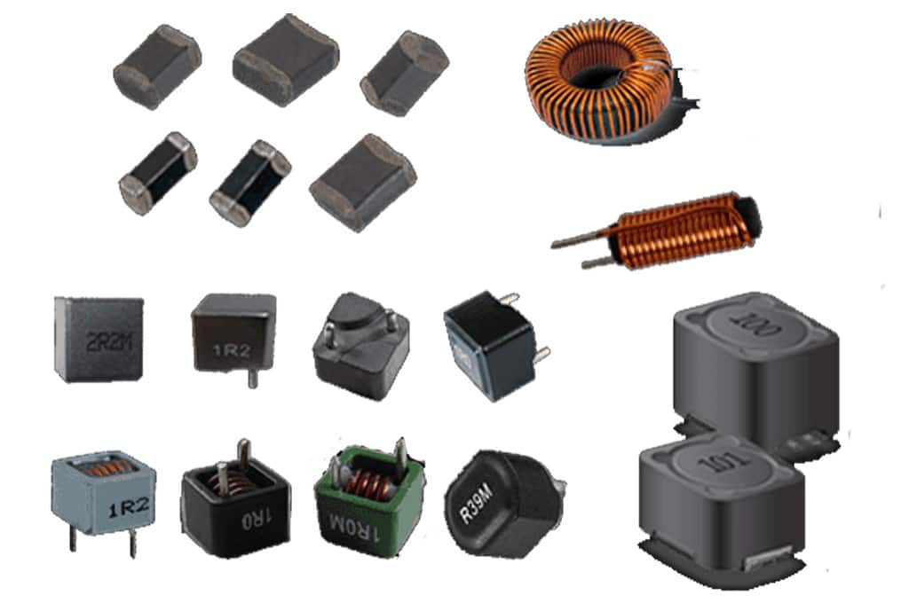
Inductance which has the symbol “L” and is measured in Henries (H), is the element used for the storage of energy in the form of an electromagnetic field. Electromagnetic energy is stored within the turns of a coil as long as a time varying current i(t) keeps flowing through the inductor.Self-inductance, L is the property of an inductor which opposes any changes in the current as defined by the constant of proportionality with the voltage generated in the coil being proportional to the rate of change of current flowing through it with respect to time.
Inductor

An inductor is another passive device that can store or deliver energy but cannot generate it. An ideal inductor is lossless, meaning that it can store energy indefinitely as no energy is lost as heat. Inductors present a low impedance path to DC current and a high impedance path to AC current. The impedance of an inductor called inductive reactance varies with frequency and in an ideal inductor the current of the AC sine wave lags the voltage by 90o.
Then we can define inductance, L as the measure of an inductor’s “resistance” to the change of current with the larger the value of L, the lower the rate of change of current. Like resistance, inductance is always a positive value.
Capacitance
Our final passive device is the capacitor. Unlike the inductor which stores its energy magnetically, a capacitor stores its energy electrostatically as a charge across its plates. A capacitor is made up of two or more conducting plates which are separated by a dielectric material. Capacitance, “C” is the property of a capacitor which opposes any changes in the voltage across it as defined by the constant of proportionality as the current flowing through it is proportional to the rate of change of voltage across it with respect to time.
Capacitor

The capacitance of a parallel plate capacitor is the ratio of the amount of charge, Qstored on its plates to the voltage, V across its plates and is measured in Farads, symbol (C), ie, C=Q/V. Capacitors present a low impedance path to AC signals but will block DC. The impedance of a capacitor called capacitive reactance varies with frequency and in an ideal capacitor the voltage of the AC sine wave lags the current by 90o. Like resistance, capacitance is always a positive value.
For simple circuits with only one passive component, either a resistor, an inductor or a capacitor we can summarise there characteristics as follows:
Passive Circuit Elements
| Passive Component | Resistance or Reactance | Phase Angle ( Φ ) |
 | R = R | 0o current is “in-phase” with the voltage |
 |  | ELI current “lags” voltage by 90o |
 |  | ICE current “leads” voltage by 90o |
Where: XL represents the inductive reactance and XC represents the capacitive reactance of an AC circuit.


