Profibus is an industry-standard communications bus protocol used in process automation and sensor networks using programmable logic controllers. Understanding how the networks function will be beneficial to any plant engineer having to deal with PLC problems.
Profibus (from process field bus) is a protocol for field bus communication in automation technology. Profibus links automation systems and controllers with decentralized field devices such as sensors, actuators, and encoders. Profibus networks exchange data using a single bus cable.
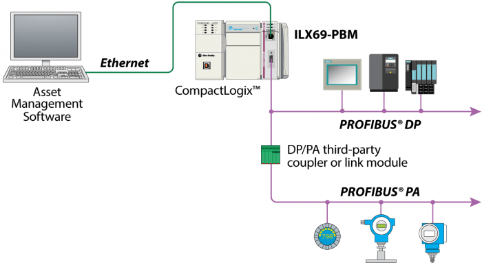
Two alternative versions of Profibus are generally used in automation: Profibus DP and Profibus PA. PA and DP contain the same protocols and both can be linked using a coupler device.
Profibus DP (Decentralized Peripherals) is normally used for data exchange with field devices like sensors and actuators through a programmable logic controller in production automation field applications.
Profibus PA (Process Automation) is used to interface measuring instruments through a process control systemin process automation applications.
An early version of Profibus was Profibus FMS, for “Fieldbus Message Specification.” Profibus FMS was intended to interface between Programmable Controllers and PLCs, sending complex data information between them.

Reference Standards
The Profibus communication is specified in IEC 61158 and IEC 61784. These standards set out the details of how each device can communicate and describe data exchange safety.
· IEC 61158 (Digital data communications for measurement and control – Communication Layers.)
· IEC 61784-1 (Communication Profiles)
· IEC 61784-2 (Realtime Ethernet RTE)
· IEC 61784-3 (Safety Communication)
· IEC 61784-4 (Security)
· IEC 61784-5 (Installation)
Importance of Profibus Protocol in Industries
Many products like PLC, drives, and instruments manufacturers offer Profibus. The advantage is that for each application, one solution, the same inventory, and the same knowledge portion can be used. Profibus can interface with 12 Mbps, which is the fastest field bus in the automation world. The network works on the master-slave scheme in which a master passes the token with its slaves and then to next station in a closed system.
Profiles
Profiles are pre-defined configurations of the functions available from Profibus for different devices and applications. The end user can interchange the same product from different vendors because of profile interoperability. Profiles are available for encoders, linear transducers, CNC machines, Drives, PLC, SCADA (Supervisory Control and Data Acquisition), various digital instruments, etc.
Profibus Troubleshooting
The configuration and programming software package is required to set up a Profibus network.
Diagnostic trouble rectification includes process related responses, built-in diagnostics mechanisms to indicate troubles on SCADA or PLC, and a Profibus interfacing break-through cable itself. Continuous monitoring of Profibus communication can identify some of the critical problems before they lead to major production loss. The diagnostics from different devices are event-triggered and generate a recordable alarm report.
Generally an engineer needs two tools to rectify the errors in network: a bus analyzer to determine the protocol quality and an oscilloscope to confirm the signal quality of the data communication, e.g. short circuit, wire breaks, termination error, etc.
A short circuit in the Profibus cable will disconnect the data communication from the master. The instrument on that node will not be destroyed in this case. The short circuit and the distance to the trouble point can be detected with an oscilloscope.
Diagnostic Function Blocks
Function blocks are capable of diagnosing each slave device. The diagnostic information can be stored in a data block. This data block further can be displayed on a SCADA PC.
Diagnostics Repeater
The repeater acts as a slave on the network and can interface diagnostics information to the master. This diagnostic data contains various fault types like Profibus cable break, conductor short circuit with the shield, terminator resistor break, nodes diagnostics, etc. The location and type of the fault on the cable can be identified in text and a graphical representation.
Power Cable Disturbance
Profibus interfacing can be disturbed by interference caused by a power cable laid near the Profibus cables. At least 10 cm air space between the Profibus and power cable should be maintained. Also proper shielding is important to prevent interference.
Important Parameter Check List During Commissioning of a Profibus Network
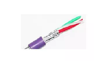
· Profibus wire polarity (A=green, B=red) should be correct.
· Ensure maximum 32 devices or less per segment.
· Avoid branch lines.
· Use only Profibus cable and connectors.
· Adequate baud rate is set with respect to cable length.
· Ensure that the address of each node is defined correctly.
· Protect the cable from short circuit and breaks.
· In case of higher transmission speed, the minimum distance between two devices shall be at least one meter.
· Multiple Profibus cables laid inside the same metal conduit gives good behavior when EMC is involved.
· One slave device can’t have two masters.
Other Related Information
Color of the Profibus DP cable
Generally the Profibus DP standard cable color will be violet, but it can have another color- for example for shipboard use it is black and for robust applications it is green.
Pin configuration on the DB9 connector
· Pin 3= red colored B line Data+ (input/output)
· Pin 8= green colored A line Data- (input/output)
· The metal casing of the connector= shield
Profibus DP to Serial Gateway
A serial gateway allows the user to communicate with any serial device with a Profibus network. It can support RS232, RS422, and RS485 serial formats without any modification in hardware.
Meaning of “GSD” File
GSD stands for “General Station Description.” The manufacturer of the devices is responsible for providing the GSD file, which describes the Profibus functionality of the device. During hardware configuration, the GSD file is required in order to have the device recognized by the controller. Integration of a new device in a configuration is done by importing a GSD file and synchronizing the address of the device.
DP Slaves in a Network
A total of 124 DP slaves can be configured for data exchange.
Each device on a Profibus network shall be assigned by address. For specifying the address, most devices have either rotary switches (decimal or hexadecimal) or DIP switches. Also a configuration tool is used for some devices to set the address.
If a slave device fails and needs replacement with the same type, the master recognizes the replaced device and with the same Profibus address.
Transmission Speed
1.5 Mbps is widely used default transmission speed. For long length cables speed should be lower to minimize the disturbances.
Bus Termination
Profibus cable ends should be terminated to stop reflections (signal resonance on the cable). Two ends of each segment should be isolated by active termination. Normally a Profibus connector comes with a built-in switch that can terminate the end.
NetTest Analysis Tool
To detect errors in Profibus DP segments, the NetTest analysis tool is widely used for line analysis. It provides information on short circuits, cable breaks, shield damage, termination mistakes, termination activated mistakes, baud rate, active node list, signal quality of slaves, etc.
A “NetTEST II” handheld diagnostic device is also available in the market.