
A microcontroller resets when a motor starts. An audio amplifier adds an irritating hum to quiet passages. A sensor produces readings that drift even though the measured temperature has not changed.
These faults can look unrelated, but the power supply is often the common cause. A circuit may be connected to a source labelled “5 V” or “12 V,” yet the voltage arriving at its pins can be noisy, sagging, overshooting, or interrupted for a few microseconds.
Electronic circuits do not use voltage as a rough suggestion. Logic thresholds, reference voltages, transistor operating points, and timing circuits all depend on power that stays within a usable range.
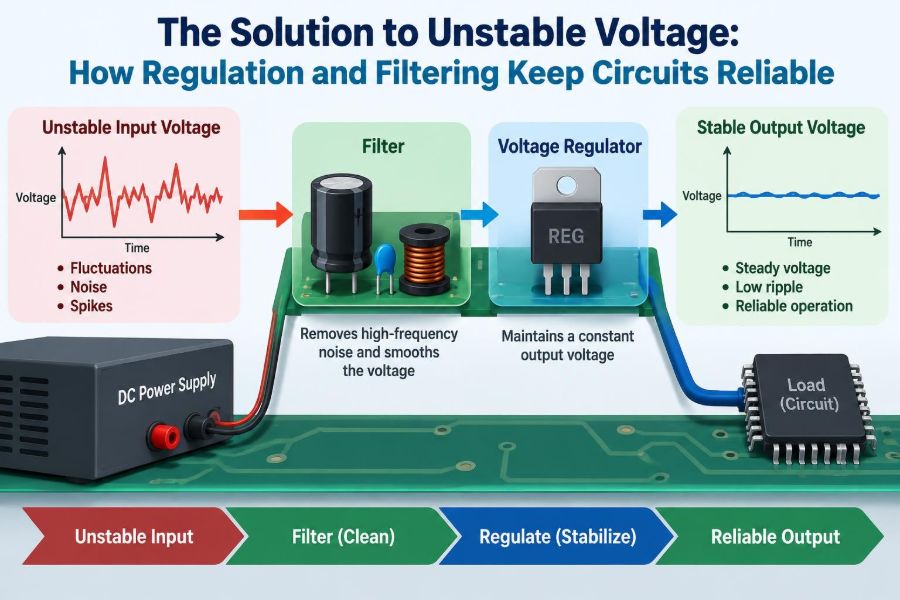
Voltage regulation and filtering are the practical tools that turn imperfect electrical energy into dependable power. They are related, but they solve different parts of the problem—and reliable designs need both.
⚡ What “Unstable Voltage” Really Means
An unstable supply is any supply whose voltage departs from what the load needs, in amplitude, frequency content, or time. The departure may be a slow change over seconds or a sharp transient lasting nanoseconds.
A multimeter showing 5.00 V does not prove that a rail is clean. Most meters average what they measure, so brief dips, high-frequency noise, and repetitive ripple can remain hidden.
Common forms of instability include ripple, random noise, load-induced voltage droop, overshoot, switching spikes, and interruptions. Each has a different origin and may require a different remedy.
🎯 Why Circuits Need a Stable Supply
Every component has operating limits. A digital IC may interpret voltage below a threshold incorrectly, while an analog circuit can turn supply variation directly into measurement or audio error.
Stability is not always about holding one mathematically perfect number. It means maintaining voltage within the tolerance required by the device, while keeping noise low enough that it does not corrupt the function being performed.
A power rail with modest ripple may be entirely acceptable for a heater or a lamp. The same rail could be unacceptable as the reference supply for a precision analog-to-digital converter.
🌊 Ripple: The Low-Frequency Problem
Ripple is a repeating variation superimposed on a DC output. It is especially familiar after AC mains have been rectified: the rectifier creates pulsating DC, not perfectly steady DC.
A reservoir capacitor charges near the peaks of that waveform and supplies the load between peaks. As it discharges, the voltage falls; the repeated fall and recharge create ripple.
Ripple grows when load current increases, the reservoir capacitance is too small, or the interval between recharge peaks is longer. Aging electrolytic capacitors can also lose capacitance and raise ripple noticeably.
📣 Noise Is Not the Same as Ripple
Noise usually describes unwanted, often higher-frequency voltage content that is not simply the regular discharge pattern of a rectified supply. It can come from switching converters, clocks, RF transmitters, motors, or external electromagnetic interference.
The distinction matters because a large capacitor that helps with low-frequency ripple may have too much inductance to handle a fast switching edge. A small ceramic capacitor near the IC can be highly effective at high frequencies while contributing little energy storage for long dips.
In practice, rails often contain both ripple and noise. Good power design considers the spectrum rather than treating all unwanted variation as one problem.
🔋 Where Supply Disturbances Begin
Instability can originate outside the product or within it. A wall adapter may have poor transient behavior, a battery may sag as it discharges, and a long cable may add resistance and inductance.
Inside the board, the load itself may be the source. Motors, relays, displays, radios, processors, and switching regulators draw changing current. Shared wiring and traces convert those current changes into voltage disturbances.
- Rectified AC sources produce periodic ripple.
- Switch-mode converters generate switching ripple and ringing.
- Motors and relays create electrical noise and inductive transients.
- Fast digital logic creates sharp current pulses.
- Long conductors create voltage drop and ringing.
📉 The Meaning of Voltage Drop
Resistance causes a straightforward loss: V = I × R. If a cable, connector, fuse, or PCB trace has resistance, changing load current changes the voltage delivered to the load.
For example, a device may work on a bench supply with short leads but reset when powered through a thin, long USB cable. The source voltage can be correct while the voltage at the device is too low during a current burst.
Resistance is only part of the story. At fast edges, inductance matters too. Inductance resists rapid change in current, which can create spikes or dips even where DC resistance is low.
🧱 Load Transients Challenge Every Supply
A load transient occurs when current demand changes quickly. A processor waking from sleep, a radio beginning transmission, or a motor starting are familiar examples.
A regulator cannot respond instantly. Until its control loop increases output current, output capacitors must provide the extra current. During that interval, the output voltage falls; when demand reduces, the rail can overshoot.
Designing for average current alone is therefore risky. Peak current, rise time, allowed voltage deviation, and the regulator’s transient response all matter.
🧭 Regulation: Controlling the Output Voltage
Voltage regulation is the process of sensing an output and adjusting energy flow to hold that output near a target. A regulator compares a scaled version of the output with an internal reference and corrects the difference.
This is a feedback system. If output voltage falls, the regulator increases its drive; if the output rises, it reduces drive. The result is not magic removal of all disturbance, but controlled correction within the limits of the circuit.
A regulator is judged by properties such as output accuracy, load regulation, line regulation, dropout voltage, current capacity, noise, efficiency, and transient response.
🪜 Linear Regulators: Quiet and Simple
A linear regulator controls output by operating a pass device like a variable resistance. The excess voltage is dissipated as heat, approximately according to P = (VIN − VOUT) × IOUT.
Linear regulators are valued for low output noise, simple external circuitry, and low electromagnetic interference. They work well when input voltage is only moderately above output voltage and current is manageable.
The main limitation is efficiency. Dropping 12 V to 5 V at substantial current wastes significant power, requiring thermal analysis and sometimes a heatsink or larger copper area.
🔄 Switching Regulators: Efficient but Noisier
A switching regulator transfers energy through rapidly switched transistors and inductors or transformers. Buck converters step voltage down, boost converters step it up, and buck-boost topologies can do both.
Because the switching device is mostly on or off, losses can be much lower than in a linear regulator. That makes switchers suitable for battery-operated equipment and high-current rails.
The trade-off is ripple, electromagnetic interference, and layout sensitivity. A well-designed switching supply can be excellent, but its inductor, diode or synchronous switches, capacitors, and loop layout are all part of the electrical design.
🧩 Low-Dropout Regulators Have a Specific Role
An LDO, or low-dropout regulator, is a linear regulator designed to regulate with a small difference between input and output. This is useful when a battery voltage approaches the required rail voltage.
“Low dropout” does not automatically mean low noise, high current, or stable with every capacitor. Datasheets specify those characteristics separately, including required output-capacitor type and equivalent series resistance.
An LDO is often placed after a switching pre-regulator to clean a sensitive, lower-current analog rail. That approach can be effective, but only if the LDO has enough input headroom under all load and temperature conditions.
🧺 Filtering: Removing What Regulation Leaves Behind
Filtering reduces unwanted AC components or transients on a power line. Capacitors, inductors, ferrite beads, resistors, and dedicated filters can each shape noise differently.
A regulator and a filter should not be treated as interchangeable. Regulation establishes and corrects the DC level; filtering provides local energy and presents impedance that opposes unwanted frequency components.
The most reliable arrangements use each where it is strongest: a suitable regulator for gross voltage control, then carefully placed filtering for ripple, fast transients, and noise isolation.
🫙 Reservoir Capacitors Store Energy
Large bulk capacitors provide an energy reserve. In a rectified supply they reduce ripple between charging peaks; near a changing load they supply current while the source or regulator catches up.
Capacitance alone is not enough. A real capacitor has equivalent series resistance (ESR) and equivalent series inductance (ESL). ESR creates an immediate voltage step when current changes, while ESL limits high-frequency usefulness.
Electrolytic and polymer capacitors are commonly used for bulk storage. Their voltage rating, ripple-current capability, temperature behavior, lifetime, and polarity must be appropriate for the application.
🧷 Decoupling Capacitors Support ICs Locally
Decoupling means placing a small capacitor close to an IC’s supply pins so it can deliver brief current pulses locally. It also prevents those pulses from spreading as strongly across the board.
A microcontroller may draw fast current bursts every clock cycle. The path from a distant supply capacitor contains inductance, so local ceramic capacitors are essential even when the main supply appears well regulated.
Placement is critical: the capacitor, power pin, and ground return must form a short loop. A capacitor placed far away may look correct on a schematic yet perform poorly on the assembled PCB.
🧱 Why Multiple Capacitor Values Are Used
Designers often use a bulk capacitor together with several ceramic capacitors. The goal is not a ritual of adding random values; it is to maintain low supply impedance across the frequencies relevant to the load.
A larger capacitor helps with slower load changes and stored energy. Smaller, low-inductance ceramics respond better to fast edges. Their exact effective behavior changes with DC bias, package size, material, and layout.
More capacitance is not always harmless. Some regulators become unstable with unsuitable output capacitance or ESR, and large inrush current can stress a source or connector.
🧲 Inductors and Ferrite Beads Block Noise Paths
An inductor resists changing current and can work with capacitors to form a low-pass filter. In switching converters, it is also the primary energy-storage element.
A ferrite bead is commonly used to impede high-frequency noise, often between a noisy digital rail and a sensitive local analog section. Its impedance is frequency dependent, and it dissipates some high-frequency energy rather than behaving as an ideal inductor.
Neither part is a universal cure. A bead feeding a load with sharp current demand can create its own local voltage dip unless adequate capacitance is provided after the bead.
🧮 RC, LC, and π Filters Compared
Passive filters trade noise reduction against voltage drop, size, cost, and transient performance. Their selection should follow the load current and the frequencies that actually need attenuation.
| Filter | Main strength | Main limitation | Typical use |
|---|---|---|---|
| RC | Simple damping and low-current noise filtering | Resistor drops voltage and wastes power | Quiet reference or sensor branch |
| LC | Low loss and stronger filtering | Can ring and needs careful damping | Converter output or power input |
| π (C-L-C) | Strong conducted-noise reduction | Can interact with source or regulator control loops | Input filtering where validated |
Filters should be verified in the real circuit. A theoretically excellent LC filter can resonate with cable inductance or a regulator’s control loop, worsening the behavior it was meant to improve.
📐 Control-Loop Stability Cannot Be Ignored
Every regulated supply with feedback has a control loop. The loop needs enough gain to correct error but must not react with the wrong timing and oscillate.
Output capacitors are often part of that loop. Their capacitance, ESR, and parasitic effects can shift poles and zeros—the frequencies where control-loop behavior changes.
If a regulator datasheet recommends a capacitor range, ESR range, or layout, treat that guidance as an electrical requirement. An oscillating regulator may produce average voltage that looks normal while creating large, harmful high-frequency variation.
🗺️ PCB Layout Is Part of the Power Circuit
At low frequencies, a schematic can seem like the whole design. At high frequencies, physical geometry determines parasitic resistance and inductance, so PCB layout becomes part of the circuit itself.
Keep high-current switching loops compact. Place input capacitors directly near a switching regulator’s input and ground return, and keep the switch node copper area controlled to limit radiated noise.
Use a continuous ground plane where practical. Splitting ground indiscriminately can force return currents through long paths and create coupling problems. The key is managing where currents flow, not simply separating labels called “analog” and “digital.”
🌍 Ground Is a Return Path, Not a Perfect Zero
Ground conductors have impedance. When multiple circuits share part of a return path, current from one circuit creates voltage variation that another circuit may see as noise.
An audio circuit, for example, can pick up a motor’s return current as audible hum or whine. A sensor reference can be shifted by digital return current and report a false measurement.
Plan high-current returns, sensitive reference returns, and measurement paths deliberately. Star-like routing is useful in some low-frequency systems, while solid planes usually provide superior high-frequency return paths on multilayer boards.
🛡️ Input Protection Comes Before Regulation
A regulator cannot safely solve every incoming fault. Reverse polarity, surge voltage, electrostatic discharge, and load-dump-like events in automotive environments may require dedicated protection ahead of the regulator.
Possible measures include fuses or resettable protection, reverse-polarity MOSFET arrangements, transient-voltage suppressors, series impedance, and input capacitors rated for the expected conditions.
Protection must be selected for the environment. A circuit intended for a short indoor cable faces different hazards from equipment connected to a vehicle electrical system or long external wiring.
🔌 Cables and Connectors Are Electrical Components
Power distribution is often designed as though wires are ideal. In reality, cable resistance causes DC loss and cable inductance produces voltage excursions when current changes rapidly.
Connectors add contact resistance, which can rise with wear, contamination, or insufficient mating force. A problem that appears only after installation may therefore be a distribution issue rather than a regulator failure.
Place bulk capacitance near remote loads, size conductors for expected current and length, and measure voltage at the load—not only at the source terminals.
🎙️ Sensitive Analog and Audio Rails Need Isolation
Analog front ends, precision references, RF circuits, and audio stages are often more sensitive to supply noise than digital logic. Their supply rejection may also vary strongly with frequency.
A practical approach is to begin with a shared efficient rail, then create quieter local branches using an LDO, ferrite bead, RC filter, or a combination chosen for the current demand and noise band.
Isolation is not an excuse to neglect grounding. A clean analog supply can still perform poorly if noisy return currents share impedance with the signal reference.
💻 Digital Systems Fail in Less Obvious Ways
Digital logic can tolerate some supply variation, but its behavior near limits is not graceful. Brownout resets, memory corruption, communication errors, and intermittent peripheral faults can result.
Enable brownout detection where available, and do not assume it replaces good power design. It detects that voltage is unsafe; it does not prevent the unsafe dip.
For processors and FPGAs, follow vendor power-sequencing guidance. Multiple rails may need to rise or fall in a defined order, and each rail may have its own decoupling requirements.
🔍 Measuring the Problem Correctly
An oscilloscope is usually the right tool for investigating rail noise and transients. Probe technique matters: a long ground clip forms an antenna and can display ringing that is mostly measurement artifact.
Use a short ground spring or a very short ground connection when examining fast events. Start with an appropriate voltage range, bandwidth limit when useful, and a trigger tied to the load event causing the suspected disturbance.
Measure at the IC supply pins and across the actual load. Compare that result with the regulator output and input to identify whether the issue is source capability, regulation, distribution, or local decoupling.
🧪 A Practical Troubleshooting Sequence
Power faults become manageable when investigated systematically rather than by randomly replacing capacitors. Reproduce the failure under the operating condition that causes it.
- Check input voltage at the regulator during the event.
- Measure the regulated output at the regulator and at the load.
- Observe current demand if suitable equipment is available.
- Look for periodic ripple, switching noise, dips, overshoot, or oscillation.
- Inspect capacitor polarity, values, solder joints, grounding, and connector condition.
- Compare the regulator circuit and layout with datasheet guidance.
Change one relevant variable at a time. Adding a temporary capacitor can reveal whether local energy storage is involved, but it should not be mistaken for a finished fix until stability and inrush effects are checked.
⚠️ Common Design Mistakes
A frequent mistake is selecting a regulator only by nominal output voltage and maximum current. Input range, dropout, thermal dissipation, transient response, capacitor requirements, and protection features may be equally decisive.
Other recurring errors include placing decoupling capacitors too far from IC pins, using undersized cables, trusting a multimeter alone, and routing noisy switch nodes near sensitive feedback or analog traces.
- Ignoring capacitor DC-bias derating in ceramic parts.
- Using a filter without considering resonance or damping.
- Assuming a ground symbol means all ground points are identical.
- Leaving no current or thermal margin for real operating conditions.
🌡️ Heat Changes the Regulation Decision
A linear regulator may be electrically correct but thermally unsuitable. Junction temperature rises with dissipated power and the thermal resistance from the silicon to surrounding air.
High temperature can trigger thermal shutdown, shorten capacitor life, and change component characteristics. The design must consider maximum input voltage, maximum load, ambient temperature, enclosure ventilation, and copper area.
Switching regulators reduce dissipation but do not eliminate thermal work. Their switches, inductor, diode where used, and input/output capacitors all have loss mechanisms.
📋 Reading Datasheets With the Right Questions
Datasheet headline specifications are only the beginning. Look for test conditions: stated ripple, accuracy, and dropout values may apply at particular currents, input voltages, temperatures, or capacitor configurations.
Pay close attention to absolute maximum ratings versus recommended operating conditions. A component surviving a brief maximum rating does not mean it is intended to operate there continuously.
Application circuits, layout examples, compensation notes, and transient-response plots often reveal more about successful implementation than a single summary-table number.
🏗️ Designing From Requirements Instead of Habit
Start by listing each rail’s voltage tolerance, average and peak current, allowable ripple, start-up behavior, operating environment, and sensitivity to noise. This turns “use a 5 V regulator” into a meaningful design requirement.
Then choose the power architecture: direct regulation, a switching pre-regulator plus LDO, separate rails, or local point-of-load conversion. The simplest architecture that meets electrical and thermal requirements is often the most robust.
Finally, allocate space for capacitors, thermal copper, measurement points, and protection from the beginning. These are not optional additions to a finished board.
✅ The Core Principle: Control Energy and Current Paths
Reliable power is achieved by controlling two things: how energy is converted and stored, and where changing currents flow. Regulation controls the DC operating point; filtering and decoupling manage unwanted variation around it.
Good component selection matters, but placement, interconnection, thermal conditions, and real load behavior determine whether the parts work together. A stable-looking schematic can fail if current loops and return paths are ignored.
The practical goal is not to eliminate every microvolt of noise. It is to deliver power whose voltage, ripple, transient behavior, and protection match the needs of the circuit under its real worst-case conditions.
When regulation, filtering, layout, and measurement are treated as one power system, circuits become far more predictable and reliable. ⚡🔧📈