
Your phone charger stays surprisingly cool while converting wall power into a safe low-voltage supply. A laptop adapter can deliver substantial power without being the size and weight of a brick. Inside a battery-powered sensor, the supply voltage may be raised, lowered, or inverted while wasting very little of the battery’s stored energy.
These familiar conveniences depend largely on switching regulators. They have become the default power-conversion method in products ranging from USB chargers and routers to electric vehicles and data-center equipment.
Linear power supplies still have a place, especially where low noise and simple behavior matter. But when engineers need efficiency, compact size, flexible voltage conversion, or long battery runtime, switching regulators usually offer a much better trade-off.
The reason is not that switching is magically lossless. It is that a carefully controlled electronic switch wastes far less energy than a device deliberately operated as a variable resistor.
⚡ The Basic Job of a Power Regulator
Electronic circuits need voltage rails that remain within an acceptable range as input voltage, load current, and temperature change. A regulator is the circuit that turns an imperfect source into a usable, controlled supply.
For example, a microcontroller may need 3.3 V while its battery ranges from 4.2 V when fully charged down to about 3 V as it discharges. Other systems may need 12 V from a 24 V source, 5 V from a USB input, or a negative rail for an analog circuit.
A power regulator must also handle transients: abrupt changes in current demand caused by processors waking up, motors starting, radios transmitting, or loads being connected.
🧱 What a Linear Regulator Does
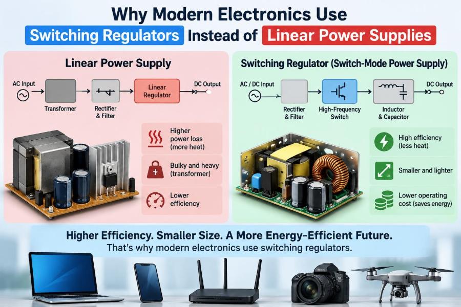
A linear regulator controls its output by placing a pass transistor between the input and output. Feedback measures the output voltage and adjusts that transistor so it drops whatever voltage is not needed by the load.
Imagine a 12 V source powering a 5 V, 0.5 A load through a linear regulator. The load receives 2.5 W. The regulator drops 7 V at 0.5 A, so it turns 3.5 W into heat.
This is electrically straightforward, and the output can be very quiet. The unavoidable limitation is that the voltage difference between input and output becomes heat whenever current flows.
🔥 Where Linear-Supply Losses Come From
The approximate dissipation in a linear regulator is easy to calculate:
Ploss = (Vin − Vout) × Iout
Its efficiency, ignoring the regulator’s own small operating current, is roughly Vout / Vin. A 3.3 V rail made from 12 V can therefore have an efficiency near 27.5% before other practical losses are considered.
That limitation is based on operating principle, not poor component selection. A better heat sink can keep the device safe, but it does not recover the energy already converted to heat.
🔄 The Key Idea Behind Switching Regulation
A switching regulator rapidly turns a transistor fully on and fully off, then uses inductors, capacitors, diodes, or synchronous transistors to transfer energy in controlled packets.
When a transistor is fully on, it ideally has very low resistance and little voltage across it. When fully off, ideally no current passes through it. In either state, its power dissipation can be low because power is voltage multiplied by current.
Real switches have resistance, transition time, gate-drive loss, and other imperfections. Even so, avoiding prolonged operation in the transistor’s partially-on region dramatically reduces loss compared with a linear pass element.
🚰 A Useful Water-Flow Analogy
A linear regulator resembles a valve that is intentionally partly closed all the time. It controls flow well, but the pressure lost across the valve is wasted.
A switching regulator is closer to a valve that opens and closes rapidly while a storage tank smooths the delivered flow. The inductor acts as an energy-storage element, and the output capacitor helps keep voltage steady between switching events.
The analogy is imperfect: electrical circuits also involve magnetic fields, feedback-loop stability, and high-frequency behavior. Still, it explains why switching circuits can control output without continuously burning the excess voltage.
📉 Why Efficiency Changes Product Design
Efficiency affects much more than an energy label. It determines heat generation, battery life, enclosure design, cable current, component ratings, and sometimes whether a design is practical at all.
If a device needs 20 W and its supply is 50% efficient, another 20 W becomes heat. If it is 90% efficient, the loss is much smaller. The exact benefit depends on load conditions, but the thermal difference can transform the mechanical design.
Lower losses can allow smaller heat sinks, less airflow, lower surface temperatures, and reduced stress on nearby capacitors and semiconductors.
🔋 Battery-Powered Products Have Little Energy to Waste
Battery-operated equipment strongly favors efficient conversion. A linear regulator can be reasonable when the input voltage is only slightly above the required output and the current is modest.
But a single-cell lithium-ion battery feeding a 1.8 V digital rail, or a 12 V battery feeding a 3.3 V processor rail, often benefits from a switching converter. The saved energy can extend useful operating time and reduce battery heating.
Switching conversion also makes better use of a battery’s discharge range. A buck-boost regulator can maintain an output even when the battery voltage moves above and below that output.
⬇️ Buck Converters Step Voltage Down
A buck converter produces an output lower than its input. It is one of the most common switching topologies, found in point-of-load supplies for processors, automotive electronics, and USB-powered devices.
Its main power path typically includes a controlled switch, an inductor, an output capacitor, and a freewheeling path. During one part of the switching cycle, inductor current rises and stores energy. During another part, the inductor releases energy to the load.
The controller adjusts the duty cycle—the fraction of time the main switch is on—to hold the desired output voltage.
⬆️ Boost Converters Step Voltage Up
A boost converter creates an output higher than its input. A power bank that raises a battery voltage to 5 V and an LED driver that produces the voltage needed by a string of LEDs are common examples.
Boost conversion is useful, but it has design consequences. Input current can become high because the lower-voltage source must provide both load power and conversion losses.
That is why battery wiring, connectors, protection devices, and input capacitors must be selected for current, not only for nominal voltage.
↕️ Buck-Boost Converters Cover a Wider Input Range
Some products must regulate through an input range that crosses the desired output voltage. A 3.3 V rail supplied by a lithium-ion cell is a classic case: the cell can be above 3.3 V when charged and below it later in discharge.
A buck-boost converter can step down when necessary and step up when necessary. Several circuit arrangements exist, including inverting and non-inverting forms, with different trade-offs in complexity, current ripple, and grounding.
The broader capability is valuable, but it usually comes with more components and a more demanding control problem than a simple buck converter.
🧲 Why Inductors Are Central Components
The inductor is the energy reservoir of many switching regulators. It resists sudden changes in current, storing energy in a magnetic field and releasing it as circuit conditions change.
Inductor selection affects peak current, ripple current, transient response, efficiency, and physical size. Its saturation current matters especially: once the core saturates, inductance can fall sharply and current may rise too quickly.
A small inductor is not automatically better. Reducing inductance can increase ripple and peak current, while increasing it can slow response or require a larger part. The controller data sheet and design equations must be considered together.
🧺 Capacitors Smooth Energy Delivery
Output capacitors supply or absorb current during switching intervals and fast load changes. Their capacitance, equivalent series resistance (ESR), voltage rating, bias behavior, and placement all affect supply performance.
Modern ceramic capacitors are compact and have low ESR, but some lose substantial capacitance under DC bias. Electrolytic and polymer capacitors may offer useful bulk energy storage, although their high-frequency behavior differs.
Input capacitors are equally important. They provide the short, high-frequency current loops demanded by the converter and reduce the disturbance sent back into the source wiring.
🎛️ Feedback Turns a Power Stage into a Regulator
Without feedback, a switching power stage would produce an output that changed with input voltage and load. A feedback network senses output voltage, compares it with a reference, and tells the controller how to alter switching behavior.
The controller may use voltage-mode control, current-mode control, hysteretic control, or another method. Each method has practical strengths involving transient response, compensation, sensing complexity, and noise sensitivity.
This feedback loop needs to be stable. A stable design corrects disturbances without excessive ringing; an unstable or poorly compensated design can oscillate, overshoot, or behave unpredictably under changing loads.
⏱️ Switching Frequency Creates a Design Trade-Off
Higher switching frequency can reduce the required inductance and capacitance, helping shrink the power supply. It can also move some audible effects above the human hearing range.
However, switching losses generally rise as frequency increases, and layout becomes more sensitive. Semiconductor transitions, magnetic-core loss, and gate-drive power all become more significant.
There is no universally ideal frequency. Engineers choose it by balancing size, efficiency, cost, electromagnetic compatibility, thermal performance, and the behavior of the intended load.
📦 Smaller Magnetics Enable Compact Electronics
Traditional mains-frequency transformers are bulky because they operate at low frequency. Switching power supplies can use much higher frequencies, allowing much smaller transformers and inductors for equivalent power transfer.
This is one reason modern chargers are compact. The size reduction is not solely due to switching frequency—semiconductor integration and improved materials help too—but high-frequency conversion is a fundamental enabler.
At low power, the difference is immediately visible. A compact USB-C charger would be difficult to realize with a conventional linear transformer and linear regulator while maintaining similar output capability.
🌡️ Heat Is a Reliability Issue, Not Just a Comfort Issue
Every watt dissipated inside an enclosure raises component temperatures unless heat is removed. Elevated temperature can shorten the service life of capacitors, accelerate material aging, and reduce semiconductor operating margin.
Switching regulators do not eliminate thermal design. Their losses occur in MOSFETs, inductors, rectifiers, control ICs, and copper traces. Yet high efficiency reduces the total heat that must be managed.
Thermal evaluation should cover worst-case input voltage, maximum expected load, ambient temperature, airflow, and startup or fault conditions. A converter that is cool on an open bench may be hot in a sealed product.
📡 The Main Cost: Electrical Noise
A switching regulator moves current quickly, and rapid changes in voltage and current generate ripple, ringing, and electromagnetic interference (EMI). This is the most visible compromise relative to a simple linear regulator.
Noise can affect sensitive analog measurements, radio receivers, audio circuits, and nearby cables. It can also cause a product to fail electromagnetic compatibility testing if not addressed during design.
Switching noise is manageable, not imaginary. It must be designed for through topology choice, component selection, PCB layout, filtering, shielding where needed, and careful measurement.
🧭 PCB Layout Often Determines Real-World Performance
A schematic can be correct while a converter still performs badly because of layout. High-current switching loops must be physically short and compact to reduce stray inductance and radiated noise.
For a buck converter, the loop involving the input capacitor, switching transistor, and return path is especially critical. The input capacitor should sit close to the power pins, not at the far end of a long trace.
Keep sensitive feedback traces away from noisy switch nodes. Use a continuous, thoughtfully managed ground reference where appropriate, and follow the IC manufacturer’s layout guidance as a starting point rather than an afterthought.
📊 Ripple Is Not the Same as Regulation Accuracy
Two specifications are often confused. Regulation accuracy describes how close the average output remains to its target under specified conditions. Ripple is the periodic variation riding on that output.
A supply can have excellent average accuracy but unacceptable ripple for a precision analog circuit. It can also have low ripple but poor accuracy if its reference or feedback-divider tolerance is unsuitable.
Measure ripple correctly. Long oscilloscope ground leads can pick up switching fields and show ringing that is largely a measurement artifact. A short ground spring or appropriate probing method gives more meaningful results.
🎧 Sensitive Analog and RF Loads Need Extra Planning
Low-noise amplifiers, data converters, precision references, and RF sections may need cleaner rails than a digital processor. That does not always mean abandoning switching conversion.
A common architecture uses a switching regulator for efficient bulk conversion, followed by filtering or a low-dropout linear regulator (LDO) near a sensitive load. The LDO removes a smaller voltage difference, so its heat loss is limited.
The right solution depends on frequency content, load current, required noise level, power-supply rejection of the load, and physical separation. A filter that helps one noise band may do little for another.
🧮 Light-Load Efficiency Can Differ from Full-Load Efficiency
Datasheet efficiency curves should be read at the currents a product will actually use. A converter that is efficient near its rated output may consume noticeable quiescent current when the load is tiny.
Many controllers use pulse-frequency modulation, pulse skipping, burst operation, or power-saving modes at light load. These methods can improve battery life but may increase low-frequency ripple or create audible behavior in some systems.
For an always-on sensor, microamp-level standby current may matter more than peak-load efficiency. For a workstation supply, sustained load and thermal capability are likely to dominate.
🔧 Synchronous Rectification Improves High-Current Designs
Older or simpler converters often use a diode as the freewheeling path. A diode has a forward voltage drop, and at high current that drop creates appreciable power loss.
Synchronous rectification replaces the diode with a controlled MOSFET. When properly timed, the MOSFET can have a much lower voltage drop, improving efficiency, especially in low-voltage, high-current buck converters.
The price is added control complexity. If both switches conduct simultaneously, a destructive input-to-ground path called shoot-through can occur. Controller timing and layout therefore matter greatly.
🛡️ Protection Features Make Supplies Safer to Integrate
Modern regulator ICs often include undervoltage lockout, cycle-by-cycle current limiting, thermal shutdown, soft start, overvoltage protection, and sometimes short-circuit behavior tailored to the topology.
These features are valuable, but they do not remove the need for system-level design. Current limiting may not protect every external component, and thermal shutdown is usually a last-resort safeguard rather than a normal operating strategy.
Check behavior during startup, overload, output short circuit, reverse input connection, and hot-plug events. A supply that works under steady conditions may still fail during these transitions.
🧪 Validation Requires More Than Seeing the Right Voltage
Reading 5.00 V on a multimeter confirms only part of the story. A useful validation plan also examines ripple, startup ramp, overshoot, load-step response, input-current behavior, thermal rise, and conducted or radiated emissions where relevant.
Test with realistic loads. A resistor is useful, but many electronic loads change current abruptly. A processor board, motor driver, or radio transmitter can reveal transient weaknesses that a fixed resistor does not.
Repeat tests across input range and temperature where the product requires it. Component tolerances and operating conditions can move a marginal design into failure.
⚖️ Linear Regulators Still Have Valid Uses
Switching regulators are not automatically the best option. A linear regulator may be the sensible choice when the input-to-output voltage difference is small, load current is low, cost and board area must be minimal, and noise requirements are stringent.
An LDO can also be easier to design and troubleshoot. It usually needs fewer components and does not create a high-frequency switch node. For a small analog reference rail, those advantages can outweigh lower efficiency.
The correct question is not “linear or switching?” in isolation. It is whether the total system requirements favor one approach or a combination of both.
🧾 A Quick Comparison of the Two Approaches
| Design consideration | Linear regulator | Switching regulator |
|---|---|---|
| Efficiency with large voltage drop | Often poor | Often high, though load dependent |
| Heat generation | Can be substantial | Usually lower for equivalent conversion |
| Component count | Often low | Usually higher |
| Noise and EMI | Generally low | Requires deliberate control |
| Step-up capability | Not available | Available with suitable topology |
| Layout sensitivity | Moderate | Often high |
| Best fit | Low-power, low-noise, small voltage drop | Efficient or flexible conversion |
🚫 Common Mistakes When Choosing a Switching Regulator
A frequent mistake is choosing an IC solely by its advertised maximum output current. Peak switch current, inductor saturation current, thermal derating, input range, and transient demand can all limit usable performance.
Another mistake is copying a reference circuit without considering the actual input source, output capacitor type, cable length, enclosure, or load behavior. Reference designs are valuable starting points, not automatic guarantees.
- Do not place the inductor or input capacitor wherever routing is convenient.
- Do not assume a higher current rating solves a poor thermal path.
- Do not ignore minimum-load, startup, and fault requirements.
- Do not evaluate noise with unsuitable probing techniques.
🧠 Choosing a Regulator Starts with System Requirements
Before selecting a topology, define the electrical environment. Identify input minimum and maximum voltage, normal and peak load current, allowed output tolerance, ripple budget, startup sequence, ambient temperature, and expected fault conditions.
Then consider practical constraints: available PCB area, component height, cost target, acoustic sensitivity, EMC requirements, and whether the load is analog, digital, inductive, or mixed.
A disciplined choice may lead to a buck converter, boost converter, buck-boost stage, isolated flyback supply, LDO, or a multi-stage combination. The topology follows the problem; it should not be chosen by habit.
🏭 Why Switching Supplies Dominate Modern Products
Modern products ask power electronics to do several things at once: accept variable inputs, deliver multiple rails, fit in tight spaces, preserve battery energy, and manage heat without large mechanical parts.
Switching regulators meet these demands because they efficiently move energy through controlled magnetic storage and rapid semiconductor switching. Their flexibility also supports the distributed power architectures used in complex digital systems, where conversion happens near each load.
The engineering effort shifts from managing unavoidable heat to managing switching behavior, layout, noise, and control-loop performance. In most medium- and high-power applications, that is a favorable exchange.
✅ The Core Principle: Control Energy Without Burning It Away
Linear regulators control voltage by dissipating excess energy. Switching regulators control voltage by storing and transferring energy in timed cycles. That distinction explains their advantage in efficiency, thermal design, battery operation, voltage flexibility, and physical size.
Switching conversion does demand competent design. Inductors, capacitors, control loops, fast current paths, and EMI cannot be treated as secondary details. When those elements are handled well, a switching regulator can provide stable power with far less waste than a linear alternative.
Linear supplies remain useful tools, particularly for low-current and noise-sensitive rails. But for the broad power needs of modern electronics, switching regulators are usually the architecture that makes the product feasible.
Modern electronics favor switching regulators because efficient energy transfer, not simple voltage dropping, is usually the decisive requirement. Choose the topology from the actual voltage, current, noise, thermal, and layout constraints—and treat the power supply as a central part of the design, not an accessory. ⚡🔋🛠️