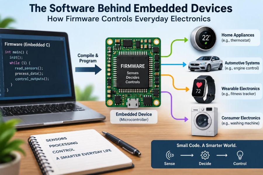

A washing machine senses an unbalanced load, changes its spin cycle, and flashes a warning. A thermostat compares room temperature with a setpoint and decides whether to run the heater. A car dashboard wakes up, checks sensors, and displays useful information before the engine is even started.
None of these products is simply “electronic.” Their components need instructions: when to measure, what to compare, which output to switch, and how to respond when something goes wrong. Those instructions are firmware.
Firmware is easy to overlook because it is rarely visible to the user. Yet it shapes how a device starts, behaves, communicates, consumes power, and survives unusual conditions.
For electronics students and working engineers, understanding firmware closes the gap between a circuit diagram and a functioning product. Hardware provides capability; firmware turns that capability into controlled behavior.
🧠 Firmware Is Software With a Physical Job
Firmware is software designed to run on dedicated electronic hardware, usually to control a specific device or subsystem. It commonly resides in non-volatile memory, meaning its instructions remain available after power is removed.
Unlike a desktop application, firmware is closely tied to pins, registers, sensors, motors, timers, and electrical limits. It cannot treat the physical world as an abstract detail: an input may be noisy, a battery may sag, or a motor may draw more current than expected.
🔍 Firmware, Software, and Hardware: A Useful Distinction
Hardware is the physical circuitry: processors, memory, transistors, connectors, sensors, and power supplies. Software is a broad term for programs and data. Firmware sits where software directly manages hardware behavior.
The boundary is not always perfect. A smart speaker may run a large operating system and many application-like features, while a small digital scale may run one compact control program. Both still depend on firmware for low-level startup and hardware operation.
📦 Where Firmware Lives Inside a Device
Firmware is often stored in flash memory, EEPROM, ROM, or a similar non-volatile technology. When power is applied, the processor begins executing instructions from a defined location, often through a startup sequence called the boot process.
Storage choice affects product design. Factory-programmed ROM is difficult or impossible to change, while rewritable flash enables updates after manufacture. The latter adds flexibility, but it also requires safe update methods and protection against unauthorized code.
⚡ What Happens When an Embedded Device Powers Up
At startup, a microcontroller does not immediately “know” what the product should do. It first resets internal state, establishes a clock source, configures memory, and begins executing its reset handler.
Early firmware then initializes essentials in a deliberate order. It may set output pins to safe states before enabling motor drivers, verify supply conditions, configure communication peripherals, and check whether an update or recovery mode is requested.
A poor startup sequence can create brief but real hazards. For example, an output pin that floats before configuration could momentarily enable an external circuit, so hardware and firmware must be designed together.
🧩 The Microcontroller at the Center
Many everyday embedded products use a microcontroller unit, or MCU. An MCU combines a processor core, program memory, working memory, timers, input/output pins, and often communication interfaces in one integrated circuit.
This integration makes MCUs practical for compact, low-power control tasks. A device does not necessarily need a powerful general-purpose computer to read a button, generate a pulse-width-modulated motor signal, and transmit a short status message.
🗺️ Registers: Firmware’s Control Panel for Hardware
Inside an MCU, peripheral functions are controlled through small memory locations called registers. Writing particular bit patterns to a register can set a pin as an output, start an analog conversion, choose a timer prescaler, or enable an interrupt.
Datasheets define these registers in detail. Firmware engineers translate product requirements into safe register configurations, while board designers ensure the electrical connections make those configurations meaningful.
📥 Reading the Physical World Through Inputs
Buttons, limit switches, temperature probes, light sensors, pressure sensors, and current monitors all provide information to firmware. Some inputs are digital, with two intended states; others are analog and must be measured as a voltage or current level.
Real signals rarely arrive perfectly. A mechanical switch can bounce between states when pressed, and an analog sensor can carry electrical noise. Firmware must interpret inputs intelligently rather than assuming every change represents a deliberate physical event.
🎛️ Analog-to-Digital Conversion Makes Measurements Usable
An analog-to-digital converter, or ADC, converts a varying analog voltage into a number that software can process. A thermistor circuit, for instance, may produce one voltage at a cool temperature and another at a warmer temperature.
The number is only as trustworthy as the complete measurement path. Reference voltage accuracy, sensor placement, resistor tolerances, filtering, grounding, and sampling timing can all influence the final value. Firmware can filter data, but it cannot fully repair a badly designed sensing circuit.
🔘 Debouncing and Filtering Prevent False Decisions
Button debouncing is a familiar example of firmware interpreting imperfect signals. Instead of acting on the first edge detected at a pin, code may wait for the signal to remain stable for a short interval before accepting the press.
For sensor data, a moving average, median filter, or simple threshold with hysteresis may be appropriate. Hysteresis means using different switching points for rising and falling values, preventing a thermostat from rapidly toggling near its target temperature.
🦾 Outputs Turn Decisions Into Action
Firmware controls outputs such as LEDs, relays, buzzers, displays, valves, heaters, and motor drivers. A processor pin usually supplies only a small signal, so external driver circuitry is commonly needed for loads requiring substantial voltage or current.
That distinction matters. Firmware might command a relay transistor on, but the circuit must include appropriate protection for the relay coil and must handle the switched load safely. Code issues a command; electronics deliver the physical action.
🌊 PWM Controls Power Without Wasting as Much Energy
Pulse-width modulation, or PWM, switches an output rapidly between on and off. By changing the fraction of time spent on, called the duty cycle, firmware can control average delivered power.
PWM is widely used for LED brightness, fan speed, DC motor control, and some power-conversion applications. The required frequency depends on the load and design goals: a frequency acceptable for a heater may produce audible noise or visible flicker in another application.
⏱️ Timers Give Firmware a Sense of Time
Timers count clock cycles independently of much of the program flow. They allow firmware to measure pulse widths, generate periodic events, create PWM signals, track timeouts, and schedule recurring tasks.
Using a hardware timer is generally more reliable than counting empty loops in code. A delay loop changes when clock frequency, compiler optimization, or surrounding code changes; a properly configured timer is tied to a known timing source.
🚨 Interrupts Handle Events That Cannot Wait
An interrupt temporarily pauses ordinary program execution so the processor can respond quickly to an event. The event might be a received communication byte, a timer overflow, an encoder edge, or an emergency fault signal.
Interrupts are powerful but demand discipline. An interrupt service routine should usually do the minimum necessary, such as recording data or setting a flag, then let the main program perform longer work. Long routines can delay other urgent events.
🔁 Main Loops and State Machines Organize Behavior
Many small embedded programs use a repeating main loop: read inputs, update logic, control outputs, and repeat. This model is effective when tasks are short and predictable.
For products with modes and sequences, a state machine makes behavior clearer. A washing machine, for example, can occupy fill, heat, wash, drain, spin, paused, and fault states, with explicit rules for moving from one state to another.
State machines reduce tangled conditional logic and make abnormal transitions easier to examine during testing.
🧵 When a Real-Time Operating System Helps
A real-time operating system, or RTOS, organizes work into scheduled tasks and provides mechanisms such as queues, semaphores, and timers. It can help when a device has multiple ongoing responsibilities, such as communications, display updates, control loops, logging, and user input.
“Real-time” does not mean merely fast. It means the system is designed to meet timing deadlines with predictable behavior. An RTOS is useful where that organization is needed, but it also increases design complexity and requires careful task-priority planning.
📊 Timing Requirements Determine the Architecture
Not every task needs the same response time. Updating a battery icon can tolerate delay, while sampling a motor-current protection signal may need a tightly bounded response. Firmware architecture should reflect those differences.
| Task example | Typical timing concern | Common approach |
|---|---|---|
| Button reading | Reject switch bounce | Periodic polling with debounce logic |
| Motor commutation | Consistent, short timing intervals | Timers and interrupts |
| Display refresh | Responsive but usually less critical | Scheduled task or main loop |
| Overcurrent response | Protect hardware promptly | Hardware protection plus firmware handling |
Where safety or equipment protection is involved, relying on firmware alone may be inappropriate. Hardware comparators, fuses, shutdown pins, and interlocks can provide faster or more independent protection.
🔄 Control Loops Let Devices Regulate Themselves
A control loop measures an output, compares it with a desired value, and changes an actuator to reduce the difference. Temperature regulation is a simple example: measure temperature, compare it with the setpoint, then adjust heating or cooling.
More demanding systems may use proportional-integral-derivative, or PID, control. Its tuning depends on the actual plant—the physical system being controlled. A controller that works well for a small fan may behave poorly with a slow thermal chamber or a high-inertia motor.
📡 Firmware Makes Components Communicate
Embedded devices commonly use interfaces such as UART, I²C, SPI, CAN, USB, or wireless protocols. Firmware configures these interfaces, formats messages, checks received data, and decides what to do when communication fails.
Electrical connection alone is not communication. Two devices also need matching speed, timing, addressing, framing, and data interpretation. A sensor may send two bytes, but firmware must know whether they represent a signed temperature, a status word, or something else.
🧾 Protocol Design Includes Error Handling
Reliable communication assumes that bytes can be lost, corrupted, delayed, duplicated, or received in the wrong order. Depending on the application, firmware may use checksums, sequence numbers, acknowledgments, retries, and timeout rules.
Retries must have limits. Repeatedly retrying a disconnected peripheral can consume processor time, fill logs, or prevent useful fallback behavior. A good design reports the fault, enters a defined degraded mode if possible, and tries recovery at sensible intervals.
🔋 Power Management Is Also a Firmware Problem
A battery-powered product may spend most of its life sleeping. Firmware can place the processor and unused peripherals into low-power modes, wake only on a timer or external event, take a measurement, transmit if needed, and return to sleep.
Power optimization is a system exercise. An efficient MCU sleep routine offers little benefit if a sensor, regulator, indicator LED, or radio remains active unnecessarily. Measuring real current in each operating mode is more useful than assuming a low-power setting solved the problem.
🛡️ Watchdogs and Fault Recovery Keep Devices Moving
A watchdog timer expects firmware to confirm periodically that normal execution is continuing. If the program becomes stuck and fails to refresh the watchdog, the timer can reset the processor.
A reset is not a complete recovery strategy. Firmware should record useful fault information when practical, restore outputs to safe conditions, avoid endless reset loops, and distinguish a transient communication glitch from a persistent hardware problem.
🧯 Safe States Must Be Designed Before Failures Occur
A safe state is the condition a device should enter when its inputs are invalid, a sensor is missing, a communication link fails, or a serious internal error is detected. For a heater controller, safe may mean disabling heat; for a door lock, the correct behavior depends on the risk context and system requirements.
There is no universal safe output. Engineers must consider the device, its environment, applicable requirements, and foreseeable misuse. The intended behavior should be documented and tested, not left to an accidental default value in code.
🔐 Connected Firmware Needs Security Boundaries
If firmware accepts commands from a network, USB port, radio link, or maintenance connector, it needs to decide which commands are authorized and which inputs are valid. Security includes protecting update paths, stored credentials, debug access, and communication data where appropriate.
A common mistake is viewing security as a feature to add after basic operation works. Decisions about processor features, memory layout, key storage, boot behavior, and service access are much easier to make during product architecture.
⬆️ Firmware Updates Fix Problems but Add Risk
Updates can correct defects, improve compatibility, and address security issues without replacing hardware. They are especially valuable for connected products and equipment expected to remain in service for years.
However, an interrupted or invalid update must not leave the device unusable. Robust approaches may verify the received image before installation, preserve a known-good version, and use a bootloader—a small startup program that can select, validate, or recover firmware images.
🧪 Testing Requires More Than “It Worked Once”
Firmware testing starts with individual functions, but real confidence comes from testing interactions: noisy inputs during communication traffic, low battery during startup, rapid user actions, disconnected sensors, and recovery after resets.
Hardware-in-the-loop testing connects software to representative electronics or simulated signals. It can reveal timing and electrical behaviors that ordinary desktop tests cannot. The closer testing is to real operating conditions, the more meaningful the result.
🐛 Debugging Means Observing Without Changing Too Much
Debuggers, serial logs, logic analyzers, oscilloscopes, and protocol analyzers each reveal different parts of a problem. A logic analyzer can show whether a digital bus has the expected timing, while an oscilloscope can expose noise, ringing, or supply dips that software logs cannot see.
Debug output itself can alter timing or memory use. When investigating a timing-sensitive fault, engineers should confirm that the observation method has not hidden the behavior they are trying to find.
🧰 Development Tools Shape the Workflow
A typical firmware workflow includes a compiler, linker, debugger, programmer, version-control system, and automated build process. The compiler turns source code into machine instructions; the linker places code and data into the device memory map.
Version control is not just for large teams. It records why a change was made, supports review, and makes it possible to compare working and failing versions. Reproducible builds also help ensure that a tested program is the one actually released.
📚 Datasheets Are Design Documents, Not Just Reference Sheets
Datasheets describe electrical limits, pin functions, timing behavior, memory organization, and peripheral configuration. Reference manuals go deeper into how an MCU’s registers and subsystems operate.
Reading them carefully prevents expensive assumptions. A pin may not be tolerant of a particular voltage, a timer may share a resource with another peripheral, or an ADC may need a limited source impedance to settle accurately during sampling.
⚠️ Common Firmware Mistakes and Better Habits
- Blocking delays: Replace long waits with timers or state-based scheduling when the device must remain responsive.
- Ignoring return values: Check whether a communication transfer, memory operation, or sensor read actually succeeded.
- Shared data errors: Protect data accessed by both interrupts and main code; assumptions about atomic access can fail.
- Magic numbers: Name constants and document units so that calibration values and limits remain understandable.
- Testing only normal use: Deliberately test power cycling, invalid data, unplugged peripherals, and boundary conditions.
These habits do not eliminate every defect. They make failures easier to detect, explain, and correct before a device reaches users.
🤝 Hardware and Firmware Must Be Co-Designed
Firmware cannot compensate for every hardware limitation, and hardware rarely reaches its potential without thoughtful code. Pin assignments, pull-up resistors, sensor ranges, memory capacity, programming access, reset circuits, and power sequencing all affect the software strategy.
Early collaboration avoids avoidable redesign. If firmware needs to distinguish several buttons using one ADC input, for example, the resistor network, expected tolerances, and voltage range must be agreed upon rather than improvised after the board is built.
🏭 From Prototype Code to a Maintainable Product
A prototype can demonstrate an idea with direct register writes and temporary test code. A production device needs clearer module boundaries, fault handling, configuration management, test procedures, manufacturing programming, and a plan for field support.
Maintainability does not require excessive abstraction. It means another engineer can identify what the code controls, understand its assumptions, reproduce its build, and change it without unintentionally breaking an unrelated feature.
🌍 Everyday Examples Reveal Firmware’s Range
In a cordless drill, firmware may read trigger position, monitor battery conditions, regulate motor drive, and stop operation if a protection threshold is reached. In a digital thermometer, it may sample a sensor, compensate or convert the measurement, update a display, and conserve battery power.
In a vehicle subsystem, firmware may exchange messages with other controllers and diagnose faults. The scale changes, but the recurring pattern remains: sense, decide, act, communicate, and recover.
🎯 The Core Principle: Firmware Connects Logic to Reality
Firmware is not merely code stored on a chip. It is the layer that converts electrical signals into decisions and decisions into physical behavior, under constraints of time, power, memory, safety, and reliability.
Strong embedded design begins by understanding the whole path: the sensor and its signal quality, the processor and timing model, the output stage and its electrical limits, the failure modes, and the user’s real environment. That systems view is what makes an electronic product predictable rather than merely functional on a bench.
The best firmware treats hardware behavior, timing, faults, and future maintenance as part of the program’s job—not as problems outside the code. That perspective is what allows everyday electronics to operate quietly and dependably. 🔌⚙️🧠