An analog multiplier is a circuit with an output that is proportional to the product of two inputs:

where K is a constant value whose dimension is the inverse of a voltage. In general we might expect that the two inputs can be both positive or negative, and so can be the output. Anyway, most of the implementations work only if both inputs are strictly positive: this is not such a limit because we can shift the input and the output in order to have a core working only with positive signals but external interfaces working with any polarity (within certain limits according to the particular configuration).
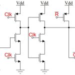
Two possible implementations will be shown. Both will be using operational amplifiers, but the first one will use diodes to get the needed relationships, the second one MOSFET transistors.
Diode Implementations
As known, using operational amplifiers and diodes it’s quite easy to obtain the logarithm and the exponential of a certain input. Remembering the property of logarithms:

we can multiply two signals first calculating their logarithm, then summing them and finally calculating the exponential of such a sum. From the point of view of mathematics, such an approach works as long as the two inputs are positive, because the logarithm of a negative number does not exist (in the real domain). We’ll see that this limit is valid for the actual circuit as well, even if the reason will be more ”physical”. The block diagram of this implementation is the following:

If we simply append the circuits for logarithm, sum and exponential we get the following configuration:

for a quick overview on the behaviour of the circuit, we’ll assume that all the resistors R have the same value. It is obviously possible to use different values to get different results, but we will not consider it here. Let us use the following notation for the relationship between current and voltage on a diode:

where VT ≃ 0.6V is the threshold voltage and Is is the current flowing through the diode if it’s inverse-polarized. If we analyse the circuit without introducing any approximation we get:

so the final output is:

as it is clear, in the output there is the multiplication we were looking for, but there is another term we don’t want. It can’t be simply considered an error because it might be as great as the multiplication element, so it has to be removed. Anyway this is an easy task, since it is necessary only to add another stage to sum exactly v1 + v2, so we will have no error. The complete multiplier circuit is the following:

where the output voltage is given by:

that’s exactly what we wanted. The circuit works as long as the following relationship is

so the inputs can be zero or slightly negative but, since RIs will be a small voltage, we are allowed to rewrite the relation simply as v1,v2 ≥ 0. From the mathematical point of view this is due to the fact that we can’t calculate the logarithm of a negative number, from a physical point of view the limit is due to the fact that we can obtain only very small currents (almost zero) inverse-polarizing the diodes.
In practical applications, the diodes are replaced with BJTs connected so to work like a diode.