
Sampling Theorem
It is the process of converting continuous time signal into a discrete time signal by taking samples of the continuous time signal at discrete time instants.


Quantization
The process of converting a discrete time continuous amplitude signal into a digital signal by expressing each sample value as a finite number of digits is called quantization. The error introduced in representing the continuous values signal by a finite set of discrete value levels is called quantization error or quantization noise.

Coding/Encoding

Anti-Aliasing Filter
When processing the analog signal using DSP system, it is sampled at some rate depending upon the bandwidth. For example if speech signal is to be processed the frequencies upon 3khz can be used. Hence the sampling rate of 6khz can be used. But the speech signal also contains some frequency components more than 3khz. Hence a sampling rate of 6khz will introduce aliasing. Hence signal should be band limited to avoid aliasing. The signal can be band limited by passing it through a filter (LPF) which blocks or attenuates all the frequency components outside the specific bandwidth. Hence called as Anti aliasing filter or prefilter. (Block Diagram).
Sample-And-Hold Circuit:
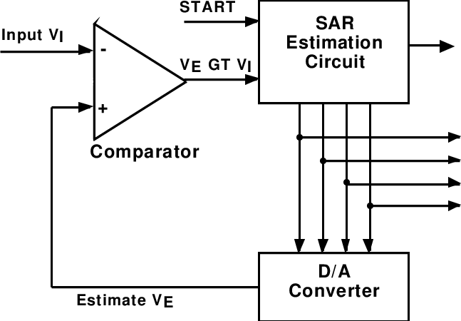
The sampling of an analogue continuous-time signal is normally implemented using a device called an analogue-to- digital converter (A/D). The continuous-time signal is first passed through a device called a sample-and-hold (S/H) whose function is to measure the input signal value at the clock instant and hold it fixed for a time interval long enough for the A/D operation to complete. Analogue-to-digital conversion is potentially a slow operation, and a variation of the input voltage during the conversion may disrupt the operation of the converter. The S/H prevents such disruption by keeping the input voltage constant during the conversion. This is schematically illustrated by Figure.

After a continuous-time signal has been through the A/D converter, the quantized output may differ from the input value. The maximum possible output value after the quantization process could be up to half the quantization level q above or q below the ideal output value. This deviation from the ideal output value is called the quantization error. In order to reduce this effect, we increases the number of bits.