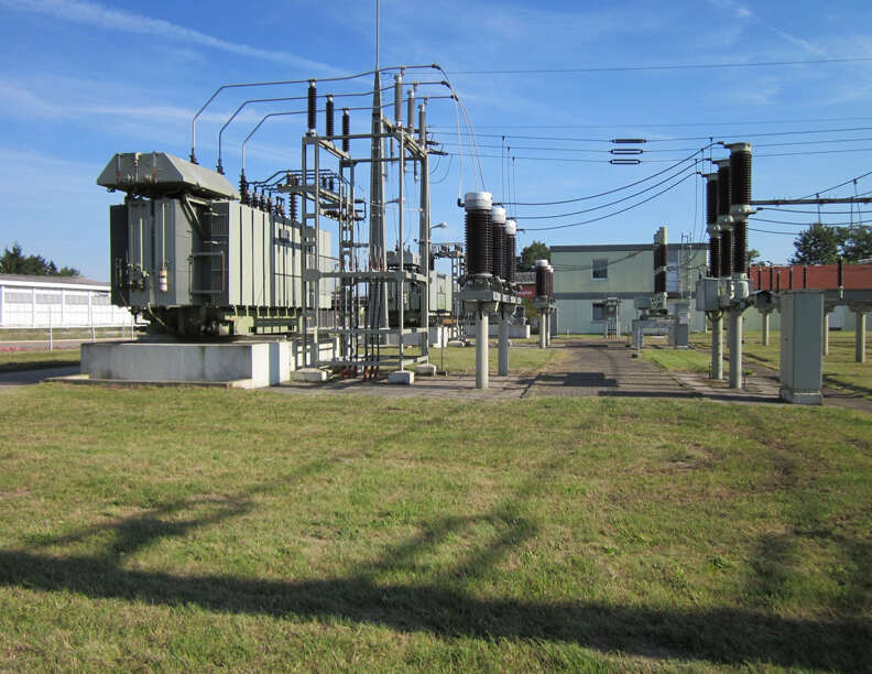
Power transformers
Transformers used in a power substations or a power system could be a bank of three single phase transformers connected in either star/delta or star/star etc., or could be a single three-phase transformer with single core. Normally for large capacity transformers, a three-phase transformer is used for the following reasons. It is lighter and cheaper, occupies less space and is more efficient.
The only disadvantage is that anything that affects the winding of one phase will affect the others also whereas in single phase transformers this is not so, as one transformer can be replaced and the operation can be continued.
The magnetic circuit of a three-phase core type transformer (Figure 1) is somewhat unbalanced, central limb having less reluctance than the outer two limbs, even though the unbalancing is not appreciable.
For all practical purposes the flux is same in all parts of the magnetic circuit and the cross-section of the yoke and the limbs should be same in order to have uniform flux density everywhere.
It is clear from Figure 3 that each phase of the shell type transformer has an independent magnetic circuit. Therefore, if for certain reasons, (a fault) one of the windings is disabled and is removed from the circuit the remaining two windings can be operated in open delta.
 Figure 1 – 3-phase core type transformer
The shell type construction as in Figure 2, with the direction of the winding the same in all three of the phases, brings in unbalancing in the flux distribution in all the limbs.
 Figure 2 – 3-phase shell type transformer – effect of winding direction
In part B of the circuit the net flux is the phasor difference of fluxes due to phase R and Y which are equal in magnitude and displaced in phase by 120° i.e., the net flux in part B is (√3/2)×φ where φ is the flux due to each phase.
Similar is the case with part C of the circuit whereas the flux in the outer limbs is φ/2.
 Figure 3 – 3-phase shell type transformer with reversed middle coil
Under this condition it is preferred to short circuit both the primary and secondary of the disabled phase so that any stray flux that may find its way into its circuit from the other two circuits is reduced to a small value. In core type of construction the magnetic circuits are not independent and this kind of short circuiting of one of the phases is not done.
The type of connections for 3-phase operation of transformers normally used are delta-star, star-delta and delta-delta.
The delta winding is used as primary, as the generated voltage is small and the current to be handled is large. This is because the phase voltage is the same as line to line voltage and the phase current is equal to line current divided by √3 .
The grounding of the neutral of the secondary of a delta-star transformer does not introduce any problem because of third harmonic, as the third harmonic component of the exciting current can flow in the primary delta winding.
When star-delta transformer is used as a step down transformer, the triple harmonic component of exciting current can’t flow in the primary winding but it appears in the delta secondary winding. In other words, the main winding takes the place of the tertiary winding.
It is, therefore, always preferrable to have at least one delta connected winding in a three phase transformer, which will eliminate the third harmonic current in the external circuit and thus will avoid the interference of power lines with the communication networks.
It is to be noted that if the flux in a transformer magnetic circuit is sinusoidal, the exciting current must contain a third harmonic component.
However, if because of transformer connections or system connections, this current can’t flow, the flux will contain third harmonic component which will induce third harmonic voltages in the transformer windings. These voltages vary between 5% to 50% of fundamental frequency voltages depending upon the type of transformer used whether core type or shell type respectively.
With star-star connections, the following systems (Figure 4, 5, 6 and 7) are considered for clear understanding:
 Figure 4 – Transformer star-star connection
In Figure 4 as the third harmonic component of current does not find a path, a third harmonic component of voltage will, therefore, be present in the line to neutral voltages even though across lines the third harmonic voltage is absent.
In Figure 5 the third harmonic components of currents do find a path and hence third harmonic component of voltages are absent.
 Figure 5 – Transformer star-star connection with grounded neutral
In Figure 6 and 7 because of presence of delta winding, the delta connection provides a path for the third harmonic currents required to eliminate the third harmonic voltages.
 Figure 6 – Transformer star-delta connection
In Figure 6, no third harmonic current will flow in the lines of the system whereas in Figure 7 the flow will depend upon the relative magnitudes of the impedances of the system and the delta winding.
However, the current is usually small and does not cause much problem with the communication networks.
 Figure 7 – Transformer star-delta connection with grounded neutral
In above Figure 4 the third harmonic voltages can be suppressed by providing a third winding connected in delta. This winding is known as tertiary winding. The e.m.fs of fundamental frequency induced in these windings will be 120° apart and will, therefore, balance, but the induced e.m.fs of triple frequency will be in time phase around the closed circuit and the resultant third harmonic current will supply the magnetising component that cannot flow in the primaries.
With star-star connection, there is instability of the neutral because of the unbalance loading condition. The potential of the physical neutral is generally at some point other than the geometric centre of the voltage triangle and is greatly affected by the characteristics of the load.
The use of tertiary along with star-star connection makes it possible to have single phase loading of the secondary of the transformer even though the primary neutral is isolated.
Refer to Figure 8 below.
 Figure 8 – Star-star connection without tertiary winding
Single phase loading in Figure 8 is not possible as this will require current in phase Y of primary and hence the current in R and B of the same winding. Since there are no opposing ampere turns of the secondary winding in phases R and B, therefore, no current can flow in Y of primary winding and hence in Y of the secondary winding.
It is to be noted here that whereas the zero sequence current and third harmonic currents resemble in some aspects they differ in the sense that whereas the flow of zero sequence currents in a circuit requires ampere turns balancing, the flow of the third harmonic currents does not require the condition of balancing ampere turns.
 Figure 9 – Star-star connection with tertiary winding


Comments are closed