When the transformer is energized, the condition initially is of zero induced E.m.f. A transient inflow of magnetizing current occurs in to the transformer. This current is called magnetizing inrush current. This current may be as great as 10 times the full load current of the transformer. This decays very slowly and is bound to operate differential protection of the transformer falsely, because of the temporary difference in magnitude of the primary and secondary currents.
The factors which affect the magnitude and direction of the magnetizing inrush current can be one of the following reasons.
a. Size of the transformer.
b. Size of the power system
c. Type of magnetic material used for the core.
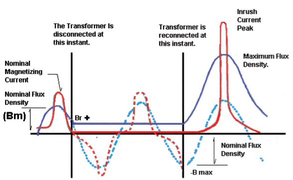
d. The amount of residual flux existing before energizing the transformer.
e. The method by which transformer is energized.
If the transformer is energized when the voltage wave is passing through zero, the magnetizing current inrush is maximum. At this instant, the current and flux should be maximum in highly inductive circuit. And in a half wave flux reversal must take place to attain maximum value in the other half cycles. If the residual flux exists, the required flux may be in same or opposite direction. Due to this magnetizing current inrush is less or more. If it is more, it is responsible to saturate the core which further increases its component.
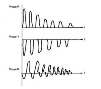
This current decays rapidly for first few cycles and then decays slowly. The time constant L/R of the circuit is variable as inductance of circuit varies due to the change in permeability of the core. The losses in the circuit damp the inrush currents. Depending on the size of the transformer, the time constant of inrush current varies from 0.2 sec to 1 sec. The waveforms of magnetizing inrush current in three phases are shown in the figure below.
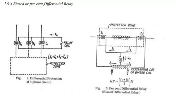
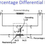
The reason for using this modification in the circulating current scheme, is to overcome the trouble arising out of differences in CT ratios for high values of external short circuit currents. The percentage differential relay has an additional restraining coil connected in the pilot wire as shown in the above figure.
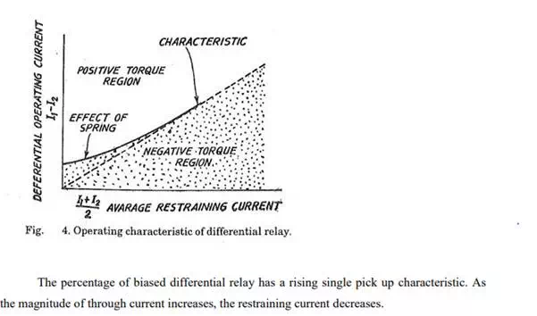
In this relay the operating coil is connected to the mid-point of the restraining coil. The restraining torque therefore is proportional to the sum of ampere turns in its two halves, i.e (I1N/2) + (I2N/2) which gives the average restraining current of (I1 + I2)/2 in N turns. For external faults both I1 and I2 increase and thereby the restraining torque increases which prevents the maloperation. The operating characteristic of the relay is given in the figure below.
The ratio of differential operating current to average restraining current is a fixed percentage and the value of which decides the nature of the characteristics. Therefore, the relay is also called ‘percentage differential relay’. The relay is also called ‘Biased differential relay’ because the restraining coil ( bias coil) biases the main flux by some additional flux.